Today there is a sustained overvoltage at around 130V. I'm told they paralleled a bunch of feeder lines because of work being done today. I found out about this because an APC Back-UPS ES 650 (BE650R-CN) malfunctioned, and I noticed the "decreasing voltage" light on the line-interactive UPS which I used as the replacement.
I was told that the BE650R-CN was beeping a lot in the morning and that it stopped supplying power. When I plugged in and turned on the UPS without any load or computer connection, it initially seemed to start normally. However, when the power on self test was supposed to finish and the UPS was supposed to switch back to external power, it instead started repeatedly clicking as if it was switching back and forth between external and UPS power.
After seeing this, I took out the battery and tested it. The battery seemed charged, at over 13V, and it was capable of powering a car headlight. Later, when I put it back in the UPS, I could power a 100W incandescent lamp. The on/off button sometimes sticks and fails to pop up, but other than that, the UPS seems fine. It supplies external power, even though the external voltage is still 130V. The upper limit is set to 139V.
I'm left wondering what happened. Did I run into a firmware bug, which was fixed by removing the battery for a while? Could the sticking power switch cause this? Is the upper voltage limit stored in non-volatile memory, or was it possibly lower before and reset by removing the battery?
Sunday, November 13, 2011


Building Rockbox simulator in Windows using Cygwin
When building the Rockbox simulator under Cygwin in Windows, an important thing to keep in mind is that the simulator is normally being cross compiled. It is being built within Cygwin using Cygwin tools, but it's built to run outside Cygwin, as a normal Windows application.
When using the
If you instead use SDL from libsdl.org, the
If you try to use the
The MinGW-w64 project provides good up-to-date MinGW compilers. Cygwin packages are available from within Cygwin setup. It's possible to use that compiler and SDL from libsdl.org by setting
With either the old Cygwin compiler or i686-w64-mingw32-gcc, there are linking problems with multiple definitions. Those can be ignored by adding
When using the
sdl package from http://download.rockbox.org/cygwin/, tools/configure doesn't need to be told about the cross-compiling because sdl-config adds the -mno-cygwin switch. That switch tells the old GCC 3.4.4 compiler to build a standard Windows application instead of a Cygwin application. The switch is only really meant for compiling parts of Cygwin which must not depend on Cygwin, but it works.If you instead use SDL from libsdl.org, the
-mno-cygwin flag won't be added and an attempt will be made to compile the simulator as a Cygwin application. This fails with many errors in /usr/include/sys/reent.h because Rockbox firmware/include/_ansi.h is included instead of /usr/include/_ansi.h.If you try to use the
-mno-cygwin flag in Cygwin gcc-4, you'll be told "The -mno-cygwin flag has been removed; use a mingw-targeted cross-compiler."The MinGW-w64 project provides good up-to-date MinGW compilers. Cygwin packages are available from within Cygwin setup. It's possible to use that compiler and SDL from libsdl.org by setting
CROSS_COMPILE=i686-w64-mingw32- when running configure.With either the old Cygwin compiler or i686-w64-mingw32-gcc, there are linking problems with multiple definitions. Those can be ignored by adding
-Wl,--allow-multiple-definition to GLOBAL_LDOPTS in Makefile.Friday, November 04, 2011
My VFD display project


A VFD is basically an array of triode vacuum tubes. Thin and almost invisible wires stretched across the display form the cathode. They emit electrons when heated. The phosphor coated display segments are anodes. When they're significantly more positive than the cathode, they attract electrons which make the segment glow. To reduce the number of pins, segments are connected together and the display is multiplexed via the grids. To light up a segment, a positive voltage needs to be applied to both the corresponding anode and corresponding grid.
Special purpose chips are typically used to drive VFDs, because required grid and anode voltages are higher than logic voltages. I chose the Allego A6812. The chip contains drivers, a shift register for loading contents serially, and latches so that output can continue while new data is loaded. The cathode also requires its own driver circuit. Because the cathode is also the heater, there is a significant voltage drop across it. If it was powered by DC, one side of the display would be brighter than the other, and so it needs to be powered by AC. I built the driver using a 555 timer and an H-bridge. Here is the driver circuit board before the display was placed on top:

I first tried out the display using an MC68705P3S which had a small bootloader for loading code into RAM via the parallel port. This was convenient because normally, code needs to be written into a 2716 EPROM and copied to the MC68705P3S, and then the microcontroller and EPROM need to be erased via ultraviolet light before the process is repeated. After this experiment, I started working on the permanent firmware, basing it on the firmware from my LED sign. Here's a photo with the unused initial circuit on the breadboard, and the start of the final circuit on perfboard:

I had a lot of TTL chips which I easily removed from a large ISA card, and I ended up adding several of those plus some other chips to the project. I added various capabilities: 6 digital outputs, 4 analog inputs (via an ADC0804 with multiplexing via a 4016), and a shift register to accelerate loading of data into the sign. (Many modern microcontrollers have similar functionality integrated into the microcontroller chip itself.) Here is a closeup of the almost completed main board:

One of the last things I added was a simple step up converter, so the VFD anode voltage is derived from the 5V supply that powers everything else:

Like with my LED sign, the case consists of quarter inch plywood. This time, I made the case by myself. Drilling edgewise into plywood isn't hard if done slowly and carefully. Here are a few photos of the case, progressing from the two boards connected together to the final painted case:


The firmware started out with the software serial code and command interpreter from my LED sign. Thanks to various optimizations, serial communication is at 1200 baud. This time, the command prompt offers only basic functionality, because I focused a lot more on functionality that's meant to be used from software running on a computer. From the command prompt, software can enter into what I call "byte mode", where commands are efficiently encoded into bytes, and they can be sent without any waiting. In that mode, the sign can multitask, scrolling a message without interruptions, while accepting other commands. That mode is also optimized for sending bar graph values and changing numbers at individual locations in the display.
The last thing I added was standalone ability to function as a clock, with multiple "alarms" changing the parallel outputs. The crystal oscillator provides good accuracy, and it was easy to calibrate the clock based on drift observed overnight.
The software controlling the sign currently runs as a Winamp DSP plugin. That is because the main function of the sign is display of Winamp status. It's not something I really need, but I really like it. When Winamp isn't playing, the bar graphs display CPU activity. This part is really useful if I turn off the monitor for some long operation, or to monitor CPU usage when running full screen software. It also helps spot anomalous activity, such as an application taking up 100% of one core.
I've used the digital outputs for various purposes. At first, I used the clock and alarm functionality to turn on my computer when it's time to wake up. Later, I used it to upload code to MC68705P3S microcontrollers for various experiments. Most recently, I used it when first trying it the TLC5940 for my RGB lamp. I didn't do as much with the analog inputs. One is connected to a photocell, and another to a thermistor, but I don't really need that data.
You can download the firmware from Dropbox and see a few more photos in the album.
Thursday, November 03, 2011
My LED sign
I made an LED sign about 14 years ago. It consists of a 72×7 array of 5mm red LEDs. The LEDs are flangeless, which allows tight packing on standard perfboard.The array was easy to build: I just bent the pins over and soldered them together, adding electrical tape to isolate between rows and columns.
 The case consists of quarter inch plywood with an acrylic front. My dad helped me with that, because it involved some tricky drilling lengthwise through plywood. I designed and built all the circuitry inside. Here's the sign with the front removed:
 You can see spacers made from bits of hardwood flooring, and a bit of
circuitry. The circuitry drives rows via transistors which have low
saturation voltage. Here's a closeup:
You can see spacers made from bits of hardwood flooring, and a bit of
circuitry. The circuitry drives rows via transistors which have low
saturation voltage. Here's a closeup:
 The circuit boards simply slide out of the front. They consist of one board with the LED array and row circuitry, and another board with the microcontroller and column circuitry. The components face outward, and the wiring is in the centre. Here is the other side of the sandwich and the empty case:
 The microcontroller controls the sign via a chain of 74HC374 octal D flip-flop chips. It outputs 8 bits, pulses the clock to latch data in the first chip and move data to the next chip, and repeats the process. While this is going on, the outputs of the last chip in the chain are disabled, which blanks the sign via the row drivers. To provide sufficient current for the rows, 7407 buffers are used. Current limiting is via the yellow DIP resistor arrays. Here is a block diagram:
 The microcontroller is a Motorola MC68705P3S, from the 6805 family. I chose it because I had the chips, programmer and toolchain from a previous project. It is a very basic 8 bit NMOS microcontroller with 112 bytes of RAM and 1668 bytes of EPROM. Unlike modern microcontrollers such as the MSP430 family, it has very few registers: the accumulator, index register, program counter, stack pointer, and condition code register. Also, output levels are similar to TTL, so the first 74374 in the chain is a 74HCT374. Here's a closeup of the area around the microcontroller:

The sign works via a serial interface at 600 baud. That may seem ridiculously slow, but it's the perfect speed for receiving new columns for horizontal scrolling. A slow speed is also required due to the microcontroller's limitations. The external oscillator is 4 MHz, but 4 cycles correspond to one instruction cycle, and all instructions take several cycles. There is no UART or DMA hardware on the chip, and everything is done via a timer interrupt and assembler code. The timer interrupt runs at three times the baud rate, so when a start bit is detected, subsequent bits can be sampled in the middle third of the bit. The electrical interface to the serial port is via a MAX232 chip at the other end of the board.
Firmware functionality is quite basic. There is a command line interface with a few functions for direct human use and a few functions which work with raw binary data. The human interface consists of an interactive drawing mode, printing of text via the on-board character generator, sign clearing, lamp test, and returning the sign contents in human-readable form via the serial interface. Due to limited EPROM space, the on-board character generator just supports one font with uppercase letters and some symbols. Other functions support scrolling up and to the left, uploading arbitrary bytes, and uploading groups of columns. These functions allow uploading of raw sign contents, where a character generator running on a computer can provide additional flexibility.
On various occasions I spent time working on PC software for the sign. I first built an interface library. Then I built a server which accepts requests from clients, along with a library that clients use to connect to the server. This allowed multiple programs to use the sign at the same time. Finally, I added support for messages which appear at most and/or at least for a specified time. This should allow the sign to be used for notifications. However, I never used it for a sustained period, because such a large notification display isn't very practical.
Besides looping a short message, there is no support for standalone operation. That means the sign is not able to display various messages with effects one would see on a LED sign that's used for advertising. I don't regret this lack of functionality, because I don't think I'd find that useful. However, if I was building something like this now, I would definitely use a more powerful microcontroller which could support that and more. I thought of replacing the MC68705P3S, but that only makes sense if I have some usage in mind.
You can download the firmware from Dropbox if you're interested. I developed it using the Motorola Portable Cross Assembler (PASM) version 1.0 toolchain.


The sign works via a serial interface at 600 baud. That may seem ridiculously slow, but it's the perfect speed for receiving new columns for horizontal scrolling. A slow speed is also required due to the microcontroller's limitations. The external oscillator is 4 MHz, but 4 cycles correspond to one instruction cycle, and all instructions take several cycles. There is no UART or DMA hardware on the chip, and everything is done via a timer interrupt and assembler code. The timer interrupt runs at three times the baud rate, so when a start bit is detected, subsequent bits can be sampled in the middle third of the bit. The electrical interface to the serial port is via a MAX232 chip at the other end of the board.
Firmware functionality is quite basic. There is a command line interface with a few functions for direct human use and a few functions which work with raw binary data. The human interface consists of an interactive drawing mode, printing of text via the on-board character generator, sign clearing, lamp test, and returning the sign contents in human-readable form via the serial interface. Due to limited EPROM space, the on-board character generator just supports one font with uppercase letters and some symbols. Other functions support scrolling up and to the left, uploading arbitrary bytes, and uploading groups of columns. These functions allow uploading of raw sign contents, where a character generator running on a computer can provide additional flexibility.
On various occasions I spent time working on PC software for the sign. I first built an interface library. Then I built a server which accepts requests from clients, along with a library that clients use to connect to the server. This allowed multiple programs to use the sign at the same time. Finally, I added support for messages which appear at most and/or at least for a specified time. This should allow the sign to be used for notifications. However, I never used it for a sustained period, because such a large notification display isn't very practical.
Besides looping a short message, there is no support for standalone operation. That means the sign is not able to display various messages with effects one would see on a LED sign that's used for advertising. I don't regret this lack of functionality, because I don't think I'd find that useful. However, if I was building something like this now, I would definitely use a more powerful microcontroller which could support that and more. I thought of replacing the MC68705P3S, but that only makes sense if I have some usage in mind.
You can download the firmware from Dropbox if you're interested. I developed it using the Motorola Portable Cross Assembler (PASM) version 1.0 toolchain.
Sunday, October 30, 2011
My MSP430 based RGB light
The Design
For a long time I thought it would be nice to have a customizable colour light, but I didn't get around to building it. This year, inspired by the MSP430 LaunchPad and my purchase of a TLC5940 with SparkFun Free Day funds I finally built it.
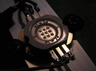
For the LED, I chose the 10W 500-Lumen Multi-Color RGB LED Emitter Metal Plate (140 degree) from DealExtreme. It's a bright LED at a good price. Similar LEDs are available from multiple Chinese sites. I chose DealExtreme because I like the way their site is organized, they have a good reputation and good prices.
Initially, I was disappointed with the TLC5940. Yes, it is a "16 channel PWM unit with 12 bit duty cycle control", as described on SparkFun. However, it requires an external clock and PWM cycle start signal, with some very specific timings when loading new PWM data and starting a new cycle. Generating all that precisely would require a lot of resources from the microcontroller.
My first circuit clocked the TLC5940 using a 555 timer, and restarted the PWM cycle using a simple R-C network. The PWM data was bit-banged from my computer, and not in any way synchronized with the PWM cycle. This worked, with the main disadvantage being that the method was slow and not suited to colour changing effects.

I spent quite a bit of time wondering how to satisfy the timings in the datasheet while having low CPU utilization and fast PWM speed. My first design used a 7474 dual D-type flip-flop. A flip-flop in toggle configuration generated SMCLK/2, and I used the CLR input to extend the GSCLK cycle at the end of the PWM cycle.

This worked well, but I ended up choosing a simpler design, connecting SMCLK to GSCLK without glue logic. BLANK was generated from TACCR0, with the timer in up mode, and output mode 3. This creates a 1 cycle pulse, using only one compare register. This does not guarantee the proper timing between the rising edges of GSCLK and BLANK, but it works perfectly. I feel it's okay because this is just a personal project, and because that GSCLK edge is after the 4096th edge which ends the PWM cycle.
For XLAT, the nicest solution would be to use the multiple TA0.0 outputs, and enable XLAT via P1SEL. However, I chose to use USI in SPI mode to load PWM data more quickly, and so the other TA0.0 output wasn't available. I instead connected another pin to XLAT, with a 1 kΩ resistor between BLANK and XLAT. When the XLAT pin outputs a low, XLAT is inhibited, and when it is an input, XLAT is pulsed when BLANK is pulsed. It's unfortunate that even the 20-pin MSP430 Value Line chips cram most special functions into the 14-pin footprint.
I wanted the light to have both computer control and a user interface. I chose a serial port for computer control. A capture/compare register can be used to build a nice software UART which is not affected by interrupt jitter. I based my code on msp430g2xx1_ta_uart9600.c from the TI sample code. I wasn't too happy with the DCO tolerances however. They are sufficient for serial communication if the other side is precise, but I wanted something that would use up well under half the error budget. (Maxim AN2141 (PDF) provides a nice explanation on the subject.) The MSP430 Value Line chips don't support high frequency crystals, and according to the datasheet, they can't even accept a high frequency external clock input. It is possible to provide a high frequency external clock, but I didn't want to rely on this undocumented feature, so I used a watch crystal. The crystal triggers the watchdog timer interrupt 4 times a second, and code calculates the length of one bit in SMCLK cycles, based on the crystal. To avoid PWM jitter, I don't actually change DCO settings like an FLL, and I set up the DCO without modulation. I chose a high frequency, just under 16 MHz, so the PWM rate is high and calculations are finished quickly. Serial communication is at 9600 baud, which allows colour changes up to about 192 times a second, with the three 12 bit values packed into 5 bytes.
With all the pins needed, it became difficult to use a 14-pin chip. Some tricks and compromises could have allowed it, but I didn't really like those ideas. I got an MSP430G2252 in a 20-pin package.
For the user interface, I used two switches and three potentiometers. One switch selects between off, serial control and local control, while the other selects between RGB, effects and HSV during local control. I had thoughts of using the comparator to measure pots, but I went for the easy solution, using the ADC10. I was disappointed at the noise, even with proper bypass capacitors. To mitigate the issue, code performs smoothing. Rotary encoders would be a better alternative, but I have plenty of pots, and quadrature encoders would need more pins. With a rotary encoder, it would be possible to avoid colour changes when changing between RGB and HSV input modes, and instead just allow further tweaking in the new mode.

The key software component of the local user interface is a multiplication routine, which multiplies two 16-bit values as fixed point numbers between 0 and 1. That same routine is used for gamma correction, HSV to RGB conversion and fading. For gamma correction, values are simply squared. A power of 2.2 might be more accurate, but squaring is close enough. HSV to RGB conversion is done via a highly optimized assembler routine, partly just because I had fun writing it. Fading via Bresenham's line algorithm would have been more efficient, but the multiplication based version was fast enough, and code size matters when only 2 KB of flash is available.
After all that was done, one pin and some flash space remained. I used the pin as a serial output, so the computer could read the current colour and potentiometer positions. Due to the special purpose pins being crammed into the 14 pin footprint, I wasn't able to directly output from TA0.2, and so the output is done from the interrupt handler. It's not ideal, but it works. I consider it to be a bonus feature.
The gamma correction in the local interface is necessary, but it created a problem. Fading requires linearly changing the value before gamma correction, but the original serial interface only allowed setting the raw PWM value, which is the result of gamma correction. For proper fading, the code would require the corresponding value before gamma correction. The serial output can help here, by allowing the current setting to be read and initial fading to be done on the computer. The serial input also allows input of values before gamma correction. For a proper fade when switching away from serial mode, code can either use that all the time or just use it once before quitting.
Originally, I had various ideas for colour changing effects. Due to the limited code size, I ended up only implementing hue spinning, with the ability to set brightness, saturation and speed. The speed selection allows a wide range, from rotations taking several minutes to such rapid rotation that the light seems steady but fast movement leaves coloured trails.

The circuit is relatively uninteresting. Mostly, it's a matter of point to point connections between chips. I used an LM317 to supply power to the MSP430 and TLC5940. At the inputs, single transistor inverters perform level shifting and provide some protection for the MSP430.
The biggest difficulty with the circuit was the TLC5940's power dissipation. With a 10W LED and 2456mW maximum power dissipation, I had to be careful to avoid overheating the chip. The light requires a 12V regulated wall wart, and I added resistors to limit the voltage drop at the chip to about 1.4V. I also mounted the chip on the underside of the circuit board and connected it to the metal bottom panel using thermally conductive putty.

According to calculations, the chip isn't close to its limit, but it's nice to have a big safety margin. The microcontroller also monitors the XERR pin via an interrupt and turns off the light if the TLC5940 overheats. I'm satisfied with the power losses due to the linear current regulation. However, considering the power losses and resultant heat dissipation, if driving a higher power LED or array I would choose three switch-mode LED drivers instead of the TLC5940.
Usage experiences
In the local interface, I mostly use the HSV input mode. It's far more convenient than the RGB mode. HSV is kind of stupid, because it ignores many perceptual factors. (The three primaries have different apparent brightness. When multiple primaries produce a colour, there is an increase in brightness and decrease in saturation. Colour does not seem to vary at a fixed speed as H is changed.) However, more complex colour spaces such as CIE LCH have many colours which cannot be reproduced via the three primaries. If the three potentiometers set L, C and H, there would be settings that are out of range. I tried it via the serial interface, and it was quite confusing. HSV to RGB conversion is also a much simpler algorithm and more suited to small microcontrollers. I have no regrets about choosing HSV.
So far, my favourite computer-based effect is a Winamp plugin which divides the spectrum into 3 zones, and sets red, green and blue values based on an exponential moving average of sound intensity in the corresponding zone. I used red for the lowest band and blue for the highest band. It's very nice with some types of music.
The Code
I'm releasing the firmware under the GNU General Public License (GPL) version 3, because I like how the GPL encourages creation of free software. I developed and compiled the code using IAR Embedded Workbench KickStart, because it offers a nice IDE for developing and debugging. Pin assignments are listed in the header file. If you want to change them, consider that many of the port 1 connections depend on the special functionality available on certain pins. You can download MSPRGB source code from Dropbox.
I'm separately releasing some code which uses the RGB lamp via a serial connection. The zip you can download from Dropbox contains librgb, a library for interfacing to the lamp, and vis_rgb, the Winamp plugin I described. I just cleaned up librgb and improved portability. I'm not protecting librgb and vis_rgb via the GPL because I don't feel it is especially worthy and because I don't want to restrict its usage.
For a long time I thought it would be nice to have a customizable colour light, but I didn't get around to building it. This year, inspired by the MSP430 LaunchPad and my purchase of a TLC5940 with SparkFun Free Day funds I finally built it.
For the LED, I chose the 10W 500-Lumen Multi-Color RGB LED Emitter Metal Plate (140 degree) from DealExtreme. It's a bright LED at a good price. Similar LEDs are available from multiple Chinese sites. I chose DealExtreme because I like the way their site is organized, they have a good reputation and good prices.

Initially, I was disappointed with the TLC5940. Yes, it is a "16 channel PWM unit with 12 bit duty cycle control", as described on SparkFun. However, it requires an external clock and PWM cycle start signal, with some very specific timings when loading new PWM data and starting a new cycle. Generating all that precisely would require a lot of resources from the microcontroller.
My first circuit clocked the TLC5940 using a 555 timer, and restarted the PWM cycle using a simple R-C network. The PWM data was bit-banged from my computer, and not in any way synchronized with the PWM cycle. This worked, with the main disadvantage being that the method was slow and not suited to colour changing effects.

I spent quite a bit of time wondering how to satisfy the timings in the datasheet while having low CPU utilization and fast PWM speed. My first design used a 7474 dual D-type flip-flop. A flip-flop in toggle configuration generated SMCLK/2, and I used the CLR input to extend the GSCLK cycle at the end of the PWM cycle.

This worked well, but I ended up choosing a simpler design, connecting SMCLK to GSCLK without glue logic. BLANK was generated from TACCR0, with the timer in up mode, and output mode 3. This creates a 1 cycle pulse, using only one compare register. This does not guarantee the proper timing between the rising edges of GSCLK and BLANK, but it works perfectly. I feel it's okay because this is just a personal project, and because that GSCLK edge is after the 4096th edge which ends the PWM cycle.
For XLAT, the nicest solution would be to use the multiple TA0.0 outputs, and enable XLAT via P1SEL. However, I chose to use USI in SPI mode to load PWM data more quickly, and so the other TA0.0 output wasn't available. I instead connected another pin to XLAT, with a 1 kΩ resistor between BLANK and XLAT. When the XLAT pin outputs a low, XLAT is inhibited, and when it is an input, XLAT is pulsed when BLANK is pulsed. It's unfortunate that even the 20-pin MSP430 Value Line chips cram most special functions into the 14-pin footprint.
I wanted the light to have both computer control and a user interface. I chose a serial port for computer control. A capture/compare register can be used to build a nice software UART which is not affected by interrupt jitter. I based my code on msp430g2xx1_ta_uart9600.c from the TI sample code. I wasn't too happy with the DCO tolerances however. They are sufficient for serial communication if the other side is precise, but I wanted something that would use up well under half the error budget. (Maxim AN2141 (PDF) provides a nice explanation on the subject.) The MSP430 Value Line chips don't support high frequency crystals, and according to the datasheet, they can't even accept a high frequency external clock input. It is possible to provide a high frequency external clock, but I didn't want to rely on this undocumented feature, so I used a watch crystal. The crystal triggers the watchdog timer interrupt 4 times a second, and code calculates the length of one bit in SMCLK cycles, based on the crystal. To avoid PWM jitter, I don't actually change DCO settings like an FLL, and I set up the DCO without modulation. I chose a high frequency, just under 16 MHz, so the PWM rate is high and calculations are finished quickly. Serial communication is at 9600 baud, which allows colour changes up to about 192 times a second, with the three 12 bit values packed into 5 bytes.
With all the pins needed, it became difficult to use a 14-pin chip. Some tricks and compromises could have allowed it, but I didn't really like those ideas. I got an MSP430G2252 in a 20-pin package.
For the user interface, I used two switches and three potentiometers. One switch selects between off, serial control and local control, while the other selects between RGB, effects and HSV during local control. I had thoughts of using the comparator to measure pots, but I went for the easy solution, using the ADC10. I was disappointed at the noise, even with proper bypass capacitors. To mitigate the issue, code performs smoothing. Rotary encoders would be a better alternative, but I have plenty of pots, and quadrature encoders would need more pins. With a rotary encoder, it would be possible to avoid colour changes when changing between RGB and HSV input modes, and instead just allow further tweaking in the new mode.

The key software component of the local user interface is a multiplication routine, which multiplies two 16-bit values as fixed point numbers between 0 and 1. That same routine is used for gamma correction, HSV to RGB conversion and fading. For gamma correction, values are simply squared. A power of 2.2 might be more accurate, but squaring is close enough. HSV to RGB conversion is done via a highly optimized assembler routine, partly just because I had fun writing it. Fading via Bresenham's line algorithm would have been more efficient, but the multiplication based version was fast enough, and code size matters when only 2 KB of flash is available.
After all that was done, one pin and some flash space remained. I used the pin as a serial output, so the computer could read the current colour and potentiometer positions. Due to the special purpose pins being crammed into the 14 pin footprint, I wasn't able to directly output from TA0.2, and so the output is done from the interrupt handler. It's not ideal, but it works. I consider it to be a bonus feature.
The gamma correction in the local interface is necessary, but it created a problem. Fading requires linearly changing the value before gamma correction, but the original serial interface only allowed setting the raw PWM value, which is the result of gamma correction. For proper fading, the code would require the corresponding value before gamma correction. The serial output can help here, by allowing the current setting to be read and initial fading to be done on the computer. The serial input also allows input of values before gamma correction. For a proper fade when switching away from serial mode, code can either use that all the time or just use it once before quitting.
Originally, I had various ideas for colour changing effects. Due to the limited code size, I ended up only implementing hue spinning, with the ability to set brightness, saturation and speed. The speed selection allows a wide range, from rotations taking several minutes to such rapid rotation that the light seems steady but fast movement leaves coloured trails.

The circuit is relatively uninteresting. Mostly, it's a matter of point to point connections between chips. I used an LM317 to supply power to the MSP430 and TLC5940. At the inputs, single transistor inverters perform level shifting and provide some protection for the MSP430.
The biggest difficulty with the circuit was the TLC5940's power dissipation. With a 10W LED and 2456mW maximum power dissipation, I had to be careful to avoid overheating the chip. The light requires a 12V regulated wall wart, and I added resistors to limit the voltage drop at the chip to about 1.4V. I also mounted the chip on the underside of the circuit board and connected it to the metal bottom panel using thermally conductive putty.

According to calculations, the chip isn't close to its limit, but it's nice to have a big safety margin. The microcontroller also monitors the XERR pin via an interrupt and turns off the light if the TLC5940 overheats. I'm satisfied with the power losses due to the linear current regulation. However, considering the power losses and resultant heat dissipation, if driving a higher power LED or array I would choose three switch-mode LED drivers instead of the TLC5940.
Usage experiences
In the local interface, I mostly use the HSV input mode. It's far more convenient than the RGB mode. HSV is kind of stupid, because it ignores many perceptual factors. (The three primaries have different apparent brightness. When multiple primaries produce a colour, there is an increase in brightness and decrease in saturation. Colour does not seem to vary at a fixed speed as H is changed.) However, more complex colour spaces such as CIE LCH have many colours which cannot be reproduced via the three primaries. If the three potentiometers set L, C and H, there would be settings that are out of range. I tried it via the serial interface, and it was quite confusing. HSV to RGB conversion is also a much simpler algorithm and more suited to small microcontrollers. I have no regrets about choosing HSV.
So far, my favourite computer-based effect is a Winamp plugin which divides the spectrum into 3 zones, and sets red, green and blue values based on an exponential moving average of sound intensity in the corresponding zone. I used red for the lowest band and blue for the highest band. It's very nice with some types of music.
The Code
I'm releasing the firmware under the GNU General Public License (GPL) version 3, because I like how the GPL encourages creation of free software. I developed and compiled the code using IAR Embedded Workbench KickStart, because it offers a nice IDE for developing and debugging. Pin assignments are listed in the header file. If you want to change them, consider that many of the port 1 connections depend on the special functionality available on certain pins. You can download MSPRGB source code from Dropbox.
I'm separately releasing some code which uses the RGB lamp via a serial connection. The zip you can download from Dropbox contains librgb, a library for interfacing to the lamp, and vis_rgb, the Winamp plugin I described. I just cleaned up librgb and improved portability. I'm not protecting librgb and vis_rgb via the GPL because I don't feel it is especially worthy and because I don't want to restrict its usage.
Synaesthesia 2.4 for Windows

Until now, the only publicly released Windows version was an old port based on Synaesthesia 1.2. The current version of Synaesthesia is 2.4, and there are many new features since 1.2. A long time ago I started working on a port of Synaesthesia as a Winamp plugin. However, I learned that GPL licensed code (Synaesthesia) can't be used in a plugin for an application that has an incompatible license (Winamp). I just created a new port based on Synaesthesia 2.4, the 1.2 Windows port and some of my code. You can download it from Dropbox. Further information is available within "Synaesthesia 2.4 Windows port readme.txt" in that zip file.
This is just a quick port I created today. There may be bugs. Please don't bother the original authors of Synaesthesia and the 1.2 port. If you run into problems, leave a comment here.
Friday, October 28, 2011
Winamp plugin which enables UAC virtualization
Some old Winamp plugins attempt to store settings in the plugin directory. This fails in Vista and Windows 7 because directories under Program Files aren't writable for ordinary users. Windows has a feature, UAC Virtualization, which redirects these writes to a folder in the user's profile (%USERPROFILE%\AppData\Local\VirtualStore). However, the manifest in winamp.exe disables this feature.
It's possible to grant write access to the directory, toggle UAC state via Task Manager, and edit the manifest in winamp.exe. However, all of these workarounds have disadvantages. Because of that, I just created a simple plugin which enables UAC. It may not execute early enough to help code which runs when Winamp starts, but it's perfect for visualization plugins which run on demand later. You can download it from Dropbox. I'm not releasing the full source because most of it is just sample code from the Winamp SDK. Enabling UAC Virtualization is easy:
It's possible to grant write access to the directory, toggle UAC state via Task Manager, and edit the manifest in winamp.exe. However, all of these workarounds have disadvantages. Because of that, I just created a simple plugin which enables UAC. It may not execute early enough to help code which runs when Winamp starts, but it's perfect for visualization plugins which run on demand later. You can download it from Dropbox. I'm not releasing the full source because most of it is just sample code from the Winamp SDK. Enabling UAC Virtualization is easy:
HANDLE token;if (OpenProcessToken(GetCurrentProcess(), TOKEN_ADJUST_DEFAULT, &token)) { DWORD v = 1;
SetTokenInformation(token, TokenVirtualizationEnabled, &v, sizeof(v));
CloseHandle(token);}
Thursday, October 27, 2011
The PL-2303 code 10 error
Some cheap PL-2303 based USB to serial adapters don't work with new drivers from Prolific. In Windows, Device Manager gives a "This device cannot start. (Code 10)" error. Prolific knows about this error and has a FAQ question about it. To me, the answer there seems to imply that these PL-2303 chips may be counterfeit.
When I ended up with such a bad PL-2303 based adapter, I investigated the issue using Snoopy Pro. It is a free open source (GPL) program which logs USB communication between the driver and device. SnoopyPro allowed me to see the requests sent by the Prolific driver, and compare responses.
Here is the request sent from Prolific v1417 driver in 32 bit Windows 7 SP1, with version 3.3.17.203 ser2pl.sys:
Here is the response from a Dynex DX-UBDB9 adapter, which works perfectly:
Finally, here's the response from the BAFO USB to RS232 Converter Adapter that I got from DinoDirect:
There's one difference: the good adapter responds with 0xAA and the bad adapter responds with zero. The information could be used to find the check in ser2pl.sys and make the driver accept the zero. However, the EULA doesn't allow that. In any case, the adapter from DinoDirect has other problems which cannot be fixed.
When I ended up with such a bad PL-2303 based adapter, I investigated the issue using Snoopy Pro. It is a free open source (GPL) program which logs USB communication between the driver and device. SnoopyPro allowed me to see the requests sent by the Prolific driver, and compare responses.
Here is the request sent from Prolific v1417 driver in 32 bit Windows 7 SP1, with version 3.3.17.203 ser2pl.sys:
URB Header (length: 80)
SequenceNumber: 10
Function: 0008 (CONTROL_TRANSFER)
PipeHandle: 00000000

SetupPacket:
0000: c0 01 86 86 00 00 02 00
bmRequestType: c0
  DIR: Device-To-Host
  TYPE: Vendor
  RECIPIENT: Device
bRequest: 01

No TransferBuffer
Here is the response from a Dynex DX-UBDB9 adapter, which works perfectly:
URB Header (length: 80)
SequenceNumber: 10
Function: 0008 (CONTROL_TRANSFER)
PipeHandle: a24f2724

SetupPacket:
0000: c0 01 86 86 00 00 02 00
bmRequestType: c0
  DIR: Device-To-Host
  TYPE: Vendor
  RECIPIENT: Device
bRequest: 01

TransferBuffer: 0x00000001 (1) length
0000: aa
Finally, here's the response from the BAFO USB to RS232 Converter Adapter that I got from DinoDirect:
URB Header (length: 80)
SequenceNumber: 10
Function: 0008 (CONTROL_TRANSFER)
PipeHandle: 856e8594

SetupPacket:
0000: c0 01 86 86 00 00 02 00
bmRequestType: c0
  DIR: Device-To-Host
  TYPE: Vendor
  RECIPIENT: Device
bRequest: 01

TransferBuffer: 0x00000001 (1) length
0000: 00
There's one difference: the good adapter responds with 0xAA and the bad adapter responds with zero. The information could be used to find the check in ser2pl.sys and make the driver accept the zero. However, the EULA doesn't allow that. In any case, the adapter from DinoDirect has other problems which cannot be fixed.
Subscribe to:
Posts (Atom)