Monday, November 19, 2012

Some bad Verbatim MCC 004 DVD+R discs

I took advantage of a deal at Staples to get a 100 pack of Verbatim MCC 004 DVD+R discs. The 50 pack was good before. Unfortunately, the 100 pack has some damaged discs. I tried to write at 8x and first noticed the problem when speed failed to rise to 8x at the usual spot. Instead, the top speed was 6x. Even verification was slowed down in some areas.

I looked at the recording surface, thinking I probably wouldn't notice anything. The damage was very obvious: many shiny points on the disk surface. When looked at more carefully, they look like short lines, so they're probably scratches. I was careful when handling the spindle and discs, so this must have happened before they were in my possession. I wonder if the spindle was subject to shock or if this is a defect from the factory.

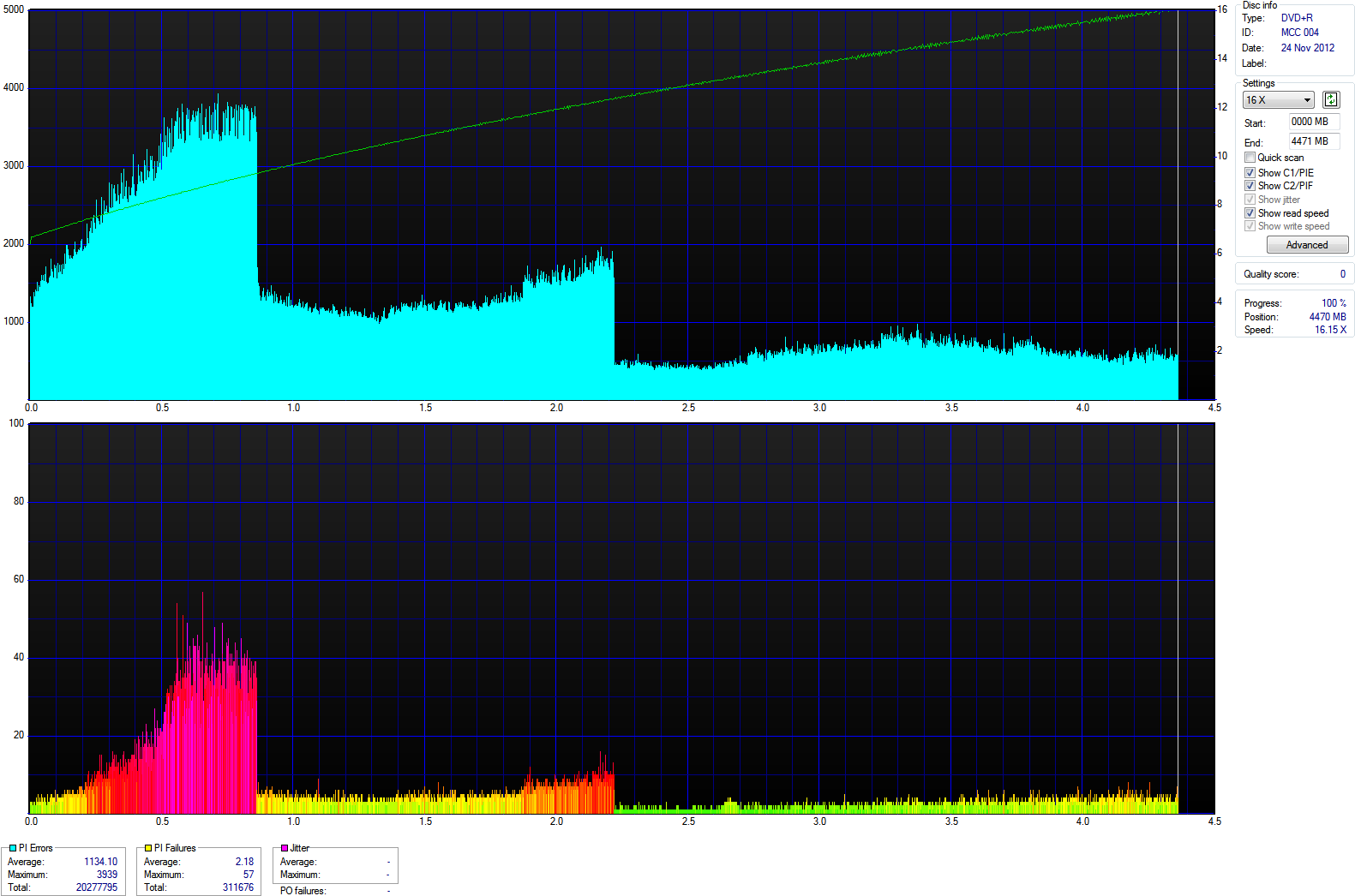
Surprisingly, the PIE/PIF scan wasn't too bad. I would have expected more PI failures. However, there certainly were a lot more PI errors than on discs from the other pack.

Update


I made a mistake in assuming that the problems I was having with the first few discs were just due to the visible spots. Even the discs without visible damage are of low quality. There are read speed decreases over large areas of the disc, and PIE/PIF scan results are much worse than with previous good Verbatim discs. After some online research, I found that these the infamous PAP6 discs. My previous good discs were PAPA. That's the start of a code you can see on the transparent area in the middle. Here are two photos comparing PAP6 and PAPA. It's hard to make good photos of this, because it's embossed transparent plastic lettering in transparent plastic. Note how the PAP6 disc has air bubbles in the plastic.


Unfortunately, according to online information, you need to open a package to see if it contains PAP6 or PAPA discs. This means Verbatim media cannot be trusted these days. What trustworthy brands are left? Taiyo Yuden? I used to think that it's weird how some people insist on that brand. Now, it seems they were right. Unfortunately, those cannot be found in local stores. Fortunately, hard drive prices have dropped so much that this is a good time to give up on optical media.

Why the drive slows down

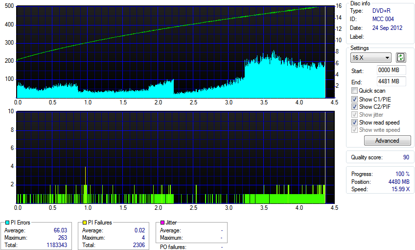
I normally do PIE/PIF scans at 5x, because of the increase in errors at higher speeds. At that speed, the PAP6 discs don't seem too terrible. The total PIF count is very high, but the maximum tends to be below 2. At 16x I get a very different picture. Here's a comparison of PAP6 and PAPA discs at 16x.


Thursday, November 15, 2012

Religious images are fine when viewed as mythology


As I was appreciating the Noah’s Ark display at the Niagara Falls Winter Festival of Lights, I asked myself a question: why was I enjoying it?

The image comes from a story about a terrible atrocity, which involved the killing of many people and animals.  It’s also something that very obviously didn’t happen according to the geological record. Believing that the Great Flood happened is delusional, and thinking that such mass killing is good is terribly wrong. Because of such things, serious worship of that God is both inaccurate and immoral.

The image wasn’t bothering me because I was looking at it as something from a myth. In other words I was looking at it as a fictional story.  That’s similar to how I was enjoying the Disney displays. With such a perspective, objections relating to religion become irrelevant.

This seems like a good thing. Openly accepting religious stories and imagery as fictional mythology is better than trying to suppress them. For example, look at various past religions. People don’t care about suppressing the Greek or Norse mythology. Instead, it’s just something that’s appreciated and played with. Things like that enrich culture.

Wednesday, November 07, 2012

Using sed to copy Firefox RES settings to Chrome

Reddit Enhancement Suite settings are stored in a JSON file in Firefox and an SQlite database in Chrome. As a result, one cannot simply copy a file to copy settings from Firefox to Chrome. I like doing twisted things with sed, so I used it to transform the JSON file into an SQL file that can be imported via sqlite3:

sed 's/[^\]"\([^\"]*\)":/\necho -n "INSERT INTO '\''ItemTable'\'' VALUES('\''\1'\'',X'\''" ; echo ~~~/g; s/`/\\`/g' store.json | sed 'sX~~~\(.*\)$X-n \1 | iconv -f UTF-8 -t UTF-16LE | od -vt x1 | sed -n '\''s/^[0-9]* //; ${ x; s/ //g; s/\\n//g; s/0a$//; s/$/'\'\\\\\'\'');/p; }; H;'\''X' | sh > res.sql
cat ~/res.sql | sqlite3 chrome-extension_kbmfpngjjgdllneeigpgjifpgocmfgmb_0.localstorage

You can find store.json in your Firefox profile. The Chrome extension ID can be seen in chrome://chrome/extensions when you enable developer mode, and then you can find the database among your Chrome configuration files. I didn't test this extensively, but it seems to work well so far.

Tuesday, October 30, 2012

Dumping SMRAM

While investingating EIST on my GA-P35-DS3R motherboard, I found P-state changes use special I/O ports which trigger system management mode (SMM). To investigate further, it is necessary to look at SMM code that runs when accesses to ports 0x880 and 0x882 are intercepted.

The first step is to obtain the code. There are two possibilities: extracting it from the BIOS and dumping it from SMRAM. I chose to dump SMRAM. That will show what is undoubtedly actually being run, and it will also dump values of variables.

Since this deals with access to memory, the P35 northbridge chip needs to be examined. Intel provides the 3 Series Express Chipset Family datasheet (PDF). The DRAM controller registers described in section 5.1 can be dumped using "sudo lspci -xxx -s 00:00.0 > P35_DRAM_registers.txt". They are listed in table 5-1.

The value of the SMRAMC register at 0x9D is 0x0A. As expected, G_SMRAME is set to enable SMRAM, but surprisingly, the D_LCK bit is not set. This means that software is free to set the D_OPEN bit and access SMRAM. The compatible SMM space bits are hard-wired, causing memory between 0xA0000 and 0xBFFFF to be used as SMRAM. This overlaps with VGA graphics memory, but that is not a problem because the northbridge can direct accesses appropriately.

The next thing to check is the ESMRAMC register at 0x9E. It's value is 0x39. The H_SMRAME bit is not set, so the low SMRAM at 0xA00000 is not remapped. However, T_EN is set, so according to TSEG_SZ, the top 1 MB of memory is also reserved for use as SMRAM. This TSEG is set as uncachable via an MTRR, so that's the part that's probably being used as SMRAM.

$ cat /proc/mtrr
reg00: base=0x000000000 (    0MB), size= 2048MB, count=1: write-back
reg01: base=0x07ff00000 ( 2047MB), size=    1MB, count=1: uncachable


One could abuse caching to mess with SMM (PDF). However, the D_LCK bit is clear, so there is no need to resort to such trickery. It should be possible to simply set the D_OPEN bit and access that memory.

The first obstacle is the CONFIG_STRICT_DEVMEM. Ubuntu and most other Linux distributions enable it, because unrestricted root access to /dev/mem is considered a security hole. With it enabled, memory at 0xA0000 can be dumped because it is within the first megabyte, but the TSEG at the end of RAM cannot be dumped.

The protection is enabled when the kernel is compiled, and it can only be disabled by recompiling or otherwise modifying the kernel. However, it's possible to load a module which provides another similar device without the protection. It would be natural to base that driver on drivers/char/mem.c, and someone has already done this, creating fmem. After compiling the module and loading it via run.sh, memory can be freely dumped via /dev/fmem.

The only remaining obstacle is the inability to access SMRAM from outside SMM. Fortunately the D_LCK bit is not set, so one can simply set D_OPEN. Here are commands displaying the SMRAMC register, setting D_OPEN, and confirming that the register changed:

$ sudo setpci -s 00:00.0 0x9D.b
0a
$ sudo setpci -s 00:00.0 0x9D.b=0x4A
$ sudo setpci -s 00:00.0 0x9D.b
4a


Now, it is possible to dump SMRAM via dd:

$ sudo dd if=/dev/mem bs=64k skip=10 count=1 of=smram.a0000.bin
1+0 records in
1+0 records out
65536 bytes (66 kB) copied, 0.00113763 s, 57.6 MB/s
$ sudo dd if=/dev/fmem bs=1M count=1 skip=2047 of=smram.tseg.bin
1+0 records in
1+0 records out
1048576 bytes (1.0 MB) copied, 0.0154848 s, 67.7 MB/s


It's probably a good idea to afterwards clear D_OPEN in the SMRAMC register, so that SMRAM has some protection again. This can be done via "sudo setpci -s 00:00.0 0x9D.b=0x0A". Feel free to try to dump the same memory while D_OPEN is cleared. Without D_OPEN, the resulting files have all bits set, showing how SMRAM cannot normally be accessed.

The dumps I got definitely contain the SMRAM. The first 64k of the TSEG dump contains structures documented in chapter 34 of Volume 3 of the Intel® 64 and IA-32 Architectures Software Developer Manual. The SMI entry point is at 0x8000. SMM starts out in a mode similar to real mode, and the code there sets up for an entry into protected mode. Saved state can be seen toward the end of the 64k segment. For example the SMBASE register is at offset 0xFEF8, containing 0x7FF00000 as expected.

That's all for now. I may post more if I find something interesting in the SMRAM.

How an I/O port leads to System Management Mode

Originally, PC I/O ports were used for accessing registers in hardware such as add-in cards or chips on the motherboard. Nowadays, they can also be used for interacting with BIOS system management mode (SMM) code. For example, the BIOS can emulate a PS/2 keyboard at the I/O port level using a USB keyboard.

When I looked at how EIST works on my GA-P35-DS3R motherboard, I found that in the _PCT method, ACPI tells the OS about ports 0x880 and 0x882:

Return (Package (0x02)
{
    ResourceTemplate ()
    {
        Register (SystemIO,
            0x10,               // Bit Width
            0x00,               // Bit Offset
            0x0000000000000880, // Address
            ,)
    },

    ResourceTemplate ()
    {
        Register (SystemIO,
            0x10,               // Bit Width
            0x00,               // Bit Offset
            0x0000000000000882, // Address
            ,)
    }
})


This tells the OS to set P-states by writing a 16 bit value to port 0x880, and to read the current P-state as a 16-bit value from port 0x882. A quick search did not find any online references to specific hardware at these ports. Considering that Windows also has DPC latency spikes when switching P-states, I wondered if accesses to these ports actually access SMM.

The chip responsible is the ICH9R southbridge. It contains various functionality for which speed is not critical. Intel provides information about this chip in the I/O Controller Hub 9 (ICH9) Family Datasheet.

The first thing to look at is section 9.3, the I/O map. Table 9-2 lists all the fixed I/O ranges, and it's easy to see that these ports do not fall into those. This leaves the variable I/O ranges in table 9-3. Most of these do not apply, because they are used for particular hardware which cannot be related to EIST. The most probable candidate is "I/O Trapping Ranges" at the bottom of the table.

I/O trapping is controlled via I/O trapping registers (IOTR0 through IOTR3), as shown in section 10.1.49. They are part of the chipset configuration registers found in memory. These don't appear at a specific location. Instead, like many variable I/O ranges, the address is set via PCI configuration registers. In particular, it is set via the RCBA register, found in the LPC interface PCI configuration registers. In Linux, one can dump these registers using "sudo lspci -xxx -s 00:1f.0 > LPC_PCI_dump.txt". There, the address can be found as a 32-bit little endian value at offset 0xF0. It is documented at section 13.1.35. Bits 31:14 correspond to bits 31:14 of the address, so my chipset configuration registers are at 0xFED1C000.

One can skip a few steps here, because the coreboot project provides inteltool. A simple "sudo inteltool --rcba > rcba.txt" command will find and dump all the chipset configuration registers. Here is the IOTR0 register in the dump:

0x1e80: 0x000c0881
0x1e84: 0x000200f0


What you see there is actually a 64-bit value: 0x000200f0000c0881. The 881 at the end definitely looks suspicious. The I/O address is 0x880, and bit 0 enables trapping and SMI. Since the address is dword-aligned, and the address mask is 0xC, the address range is 0x880-0x88F. The byte enable mask is 0xF, enabling trapping regardless of what bytes are accessed. Finally, the read/write mask is 1, making the trapping operate on both reads and writes.

This clearly shows how Award BIOS F13 for the Gigabyte GA-P35-DS3R motherboard makes the OS trigger system management mode for changing processor P-states. The next step is dumping SMRAM.

Exploring EIST


My desktop PC has a Gigabyte GA-P35-DS3R motherboard and Core 2 Quad Q6600 stepping 11 CPU. The BIOS is the latest official release, F13.

The latency issue

On this and some other Gigabyte motherboards, enabling "CPU EIST Function" in "Advanced BIOS Features" causes audio interruptions in Windows 7. This is due to latency spikes which can be seen using the DPC Latency Checker (dpclat). They can be investigated and tracked down using xperf. The rest of this document is not specifically focused on this issue; it only served as the initial motivation.

About C1E

When the option is disabled, I can still see frequency and voltage changing between the two different P-states supported by the CPU. This is probably only due to the enhanced C1 (C1E) state, which is enabled via a separate "CPU Enhanced Halt (C1E)" BIOS option. It means that when all the cores are halted, the CPU goes to its lowest P-state. This is automatic, so there is no need for the OS to do anything special. It can be disabled in Windows by disabling the C1E option in RealTemp. I don't know how that works. The Intel® 64 and IA-32 Architectures Software Developer Manual documents MSR_POWER_CTL with a C1E Enable bit, but that MSR does not exist in the Q6600.

SpeedStep in Linux

In Ubuntu 12.10 with kernel 3.5.0-17-generic, it is obvious that there is no CPU frequency control when EIST is disabled in the BIOS. The /sys/devices/system/cpu/cpu?/cpufreq directories don't exist, and everything shows that the CPU is stuck at 2.4 GHz. However, it's still possible to see the voltage vary using sensors because of C1E.

If EIST is enabled in the BIOS, frequency control is enabled in the kernel. There is an "ACPI: Requesting acpi_cpufreq" message at startup, and the cpufreq directories appear. It's possible to take manual control of the frequency by changing the governor.

for i in /sys/devices/system/cpu/cpu?/cpufreq/scaling_governor ; do sudo sh -c "echo userspace > $i" ; done

It then becomes possible to manually set the frequency. For example, this shows how to switch between the two states supported by my Q6600:

for i in /sys/devices/system/cpu/cpu?/cpufreq/scaling_setspeed ; do sudo sh -c "echo 2400000 > $i" ; done
for i in /sys/devices/system/cpu/cpu?/cpufreq/scaling_setspeed ; do sudo sh -c "echo 1600000 > $i" ; done


Note how this sets all of the cores. The setting is for each individual core, but the actual change is for the whole CPU. The CPU will choose the highest selected frequency and voltage out of all the cores. So, to choose 1.6 GHz, all cores need to be set to that. If even one core is set to 2.4 GHz, all cores will run at that speed.

This undoubtedly works. The performance difference is easy to measure. It's also possible to use sensors to see how at 1.6 GHz, the voltage stays low even at full load. To go back to automatic control, just select the ondemand governor:

for i in /sys/devices/system/cpu/cpu?/cpufreq/scaling_governor ; do sudo sh -c "echo ondemand > $i" ; done

Note how when the ondemand governor is selected, all the scaling_setspeed files contain <unsupported> instead of a frequency. Other options are also available.

The MSRs

EIST can also be controlled and observed via model-specific registers in the CPU. It's all documented in the Intel Software Developer Manual. The frequency and voltage can be set via IA32_PERF_CTL and the current state can be read via IA32_PERF_STATUS.

For accessing MSRs in Linux, msrtool is useful. The version available in Ubuntu is old, so it needs to be compiled from source. If you get an error about pci.h, install libpci-dev. For accessing MSRs via /dev/cpu/?/msr, the msr module must be loaded.

For controlling EIST, c2ctl is a more convenient tool. It can set multiple cores with one command, and it can even enable EIST via IA32_MISC_ENABLE. As a result, it can be used to change the CPU speed even when EIST is disabled in the BIOS and kernel. It can even be used to set frequencies and voltages between the two officially supported states. However, it cannot set anything outside this range, because the CPU is locked.

The role of ACPI

The Linux kernel does not actually know how to use EIST. Instead, it is just told by the BIOS via ACPI that certain states can be set by writing certain values to certain addresses. This is why the driver is called acpi_cpufreq. The ACPI tables provided by the BIOS can be dumped, extracted and disassembled:

sudo acpidump > acpidump.out
acpixtract acpidump.out

iasl -d DSDT.dat
iasl -d SSDT.dat

This results in DSDT.dsl and SSDT.dsl files containing ACPI Source Language, which is a programming language and not a simple description. Information is available in the ACPI specification and elsewhere.

My BIOS provides the same DSDT table regardless of whether EIST is enabled. However, the SSDT table is only provided when EIST is enabled. A quick look inside the SSDT.dsl shows code relating to EIST, but it's not all there. The start of the file contains an SSDT array containing memory addresses, and the rest of the file contains code which loads more code from these addresses. The kernel shows ACPI: Dynamic OEM Table Load messages relating to this during startup. It's possible to use those messages to dump the tables:

dmesg | sed -n "s/^.*SSDT 0000\([^ ]*\) \([^ ]*\) .*PmRef *\(Cpu[0-9][^ ]*\) .*$/sudo acpidump -a 0x\1 -l 0x\2 > ssdt_\3.aml/p" | sh
for i in ssdt_*.aml ; do iasl -d "$i" ; done 


Now all the code is available for examination. The ssdt_Cpu?Ist files contain power management functions for each particular core. The _PCT method shows where to write to change P-states and where to read the current state.  The _PSS method gives a list of the available P-states, including information about them and the value to write to the location given by _PCT. For more information about what's going on here, check out this message board thread and the ACPI specification. What the code needs to do is actually very simple. It's just complicated by the need to support various different configurations.

In my case, there are no tables for C-states. This is because the Q6600 CPU only supports C1E, and the OS does not need to do anything special to use it.  Deeper sleep such as C2 requires a read from a chipset I/O port, and those ports would be described in a table.

It is possible to integrate all the SSDT code into the DSDT file. The files cannot simply be concatenated and some editing is needed. The code inside the DefinitionBlock in other files can go into the DSDT DefinitionBlock. Also, the TLD0 variable and the whole "If (LEqual (TLD0, 0x00))" block can be removed, because once the code is integrated there is no need to load it externally. This means the code will be available even if the OS does not show a need for it when calling the _PDC method, but that should not be a problem.

When compiling the DSDT, there can be errors due to bad code from the motherboard manufacturer. Gigabyte chose to use the Microsoft compiler which allows errors that the Intel compiler does not. I found a message board post showing the fixes needed for my motherboard.

The best way to load the custom DSDT is via grub. Recompiling should be a last resort, because it needs to be repeated every time when upgrading the kernel.

When EIST is disabled in the BIOS, the custom DSDT is sufficient to make Linux load the acpi_cpufreq driver and pretend that it can be used. However, the attempted CPU frequency changes have no effect. One obvious issue is that EIST is disabled via IA32_MISC_ENABLE. That can be fixed via c2ctl, but it is not sufficient to EIST work.

What's at ports 0x880 and 0x882?

The DSDT tells the operating system that performance states can be set by writing to port 0x880, and that the current state can be read from port 0x882. That is weird. I don't know what hardware resides at that location. Maybe it's not real hardware, and it instead runs System Management Mode code from the BIOS. This could explain the latency spikes I observed in Windows. Maybe that code takes a long time to run. I may investigate those ports more some other day. (Update: Yes, these ports trigger SMI and lead to SMM.)

It's possible to write to the MSRs instead. The _PCT method needs to be changed to return MSR addresses using FFixedHW:

Method (_PCT, 0, NotSerialized)
{
    Return (Package (0x02)
    {
        ResourceTemplate ()
        {
            Register (FFixedHW,         // PERF_CTL
                0x10,                   // Bit Width
                0x00,                   // Bit Offset
                0x00000199              // Address
                ,)
        },

        ResourceTemplate ()
        {
            Register (FFixedHW,         // PERF_STATUS
                0x10,                   // Bit Width
                0x00,                   // Bit Offset
                0x00000198,             // Address
                ,)
        }
    })
}


Also, it is important to make sure that the _PSS method returns actual MSR values consisting of the FID and VID instead of some other value. With these changes, EIST works after it is enabled via "sudo c2ctl 0-3 -e". The ACPI language doesn't seem to have the ability to access an MSR, I cannot simply enable EIST via some code in the DSDT.

Perhaps Windows would not have DPC latency spikes if it used MSRs instead of I/O ports? I attempted use my altered DSDT with Windows 7 by booting via Grub, but that resulted in an ACPI blue screen of death. Maybe Grub can't successfully change the DSDT for Windows?

The Performance Penalty

EIST has a cost. The CPU will increase speed when needed, but this is not instantaneous. A long process will effectively run at the maximum CPU speed, but shorter processes won't. Here is a totally artificial example:

time for (( i=0 ; i<1000 ; i++ )) ; do cat /dev/null ; done

Here, the ondemand governor is over 20% slower than when speed is manually set to 2.4 GHz. It's unlikely that the speed of running 1000 processes that do nothing matters, but it's possible that things like configure scripts are slowed down.

I guess I will continue as before, just using C1E and not using EIST. I don't really notice a difference in fan RPM and temperature, and I'd rather not have any performance penalty. I doubt that there's a big difference in power usage, because if the CPU runs at a higher speed, that means it gets work done quicker and spends more time in C1E. I nevertheless think this exploration was worthwhile, because it has demystified ACPI for me.

Monday, October 22, 2012

Running Linux from RAM

Computers nowadays usually have a lot of memory, and a basic Linux system can fit in RAM. I started out by installing from the Ubuntu 12.10 Minimal CD. There I chose x86, because it's smaller and the speed difference isn't very dramatic.

I performed a normal installation into a 1 GB partition. Because of the small size, Lubuntu and even tasksel were out of the question, and manual package selection was necessary. Initially, I was disappointed, because just the minimal install took up over 700 MB. After uninstalling Linux headers, I could easily fit LXDE basics plus Firefox. The hardest part was manually configuring wireless, but that's another story.

I now had a usable system, and it was time to get it running from RAM. I did that from a shell started by adding init=/bin/sh to the kernel command line. Here is a script. The comments explain what is being done.

# Script to copy / to tmpfs and continue boot from there
# Do not run this from a child shell. Use ". ramify" or exec.
# The shell running this script must be the only process on the system.
#
# Ensure this runs in /
cd /
# Create and mount tmpfs file system for /
mount -t tmpfs tmpfs mnt
# Copy everything from / filesystem to tmpfs
# Tar will restore proper owners and permissions when run as root
# FIXME: This is very slow because it reads / in many small pieces
# TODO: Add --exclude to prevent copying unneeded stuff
tar --one-file-system -c . | tar -C /mnt -x
# Move other mounts
mount --move dev mnt/dev
mount --move proc mnt/proc
mount --move run mnt/run
mount --move sys mnt/sys
# Create fstab with just new root file system
sed -i '/^[^#]/d;' mnt/etc/fstab
echo 'tmpfs / tmpfs defaults 0 0' >> mnt/etc/fstab
# Pivot root using instructions from pivot_root(8) man page
cd mnt
mkdir old_root
pivot_root . old_root
# Old root can only be unmounted once sh running from old root
# finishes. Continue startup normally using init.
exec chroot . bin/sh -c "umount old_root ; exec sbin/init"

Saturday, October 20, 2012

Using the ATI Remote Wonder in Windows 7

The ATI Remote Wonder only has drivers for Windows XP and earlier versions. The latest XP driver is version 3.04. It's still available from AMD. If it becomes unavailable, look for 3-04_rw_enu.exe for English-only and 3-04_rw.exe for multilanguage.

I installed from 3-04_rw_enu.exe. Everything seemed fine before the reboot, but afterwards I saw the following:

C:\Program Files\ATI Multimedia\RemCtrl\drivers\wdreg_gui.exe Error
Error updating the driver (hid:*WINDRVR6) with the INF file: The system cannot find the file specified.


The command reporting the error was:

"C:\Program Files\ATI Multimedia\RemCtrl\drivers\wdreg_gui.exe" -inf "C:\Program Files\ATI Multimedia\RemCtrl\drivers\ATIRWVD.INF" install

This error may relate to Jungo WinDriver. The program ran, but there was no tray icon and the remote did not work. An optional Remote Wonder update became available on Windows Update, but that did not make the remote work.

To make it work, I installed the X10 drivers from x10drivers.exe. The installer also contains drivers for other X10 hardware, but that is not a problem. It fails to create an Install.log file for uninstall, so uninstall fails. If you want to fix that, grab it from %Temp% by creating a hard link to the right randomly named and currently in use temporary file when the installer says the install succeeded. That's not of much use though, because using it, the uninstaller just deletes a directory with a few internet shortcuts and removes the uninstall entry. If you want to remove the driver, you could remove it from the Driver Store using pnputil, but that's neither necessary nor recommended.

There may be another alternative, setup_rwplus_xp_vista.exe, but I don't recommend it. That file contains the same version of X10 drivers, but it also creates a bunch of HID devices in Device Manager that are difficult to get rid of. The installer also fails to create Install.log, and it doesn't even pause to let you grab the file from %Temp%.

Finally, you may want to customize some things. There's a site with various plugins for the Remote Wonder software. If you want to customize almost any key, then install the RW Key Factory plugin. For total freedom to customize any key, or if you want to try an alternative to the ATI program, try RW Key Master.

Friday, October 19, 2012

Controlling a device via the IR receiver port

When I first set up MythTV, I changed channels on the Huawei DC730 cable box using LIRC and the simple transmitter circuit. This means the Linux kernel was toggling a serial port pin at 38 kHz to generate the IR carrier frequency. This may sound ridiculous, but it actually works well. As long as the LED was properly aligned, the signal always got through.

The DC730 comes with an infrared receiver which connects via a standard headphone jack. It allows the unit to be put in some convenient out of the way place, with just the tiny receiver placed in a strategic position for receiving light from the remote. Of course, this same port can also be used to electrically control the DC730.

I could guess the pinout. The exposed sleeve needed to be ground. To minimize the risk of shorts, it would be best to power the receiver via the tip. This leaves the sleeve (middle section) for the IR signal. I confirmed all this with a multimeter. The DC730 supplies just under 5V via the tip. The sleeve is also near 5V, but the voltage is lower, and attempts to draw some current via a resistor show that there's much less of a voltage drop when drawing current from the tip.

Knowing this, it's easy to try using the receiver. It works just like most other IR receivers. The output is normally high, and it goes low when an IR signal modulated at the right frequency is detected. The internals are probably similar to this Hauppauge receiver. It could probably work with my PVR-250 card, though I never tried this because the lirc_i2c kernel module isn't included in Ubuntu and I don't have the Hauppauge remote for the ir-kbd-i2c module.

For supplying a signal from the computer, I chose to use an optocoupler. This is not really necessary because cable ground ties together DC730 and computer grounds. However, I have plenty of optocouplers, and I might as well have the extra security and ground loop avoidance. I chose a TIL-113, which has a darlington on the output. This allows for a lighter load on the serial port, and the slower operation of the darlington is not a problem with slow remote control signals. On the serial port side, the circuit is much like the simple LIRC transmitter. The DC730's internal pullup resistor wasn't sufficient to get a clean signal, so I added a pullup resistor. On the software side, all that's needed is the softcarrier=0 parameter for the lirc_serial module. This tells the module to simply keep the output high instead of pulsing it at the carrier frequency.

While it's nice to know that the kernel won't have to generate the carrier, the main advantages are more practical. There is no need to worry about alignment and IR leakage anymore. Setup involves simply plugging in a cable.

Thursday, October 18, 2012

My oscilloscope failed, but the fix was simple

I have an old Telequipment D54 oscilloscope. I rarely use it nowadays, but it's a big help when I actually need it.

When I turned it on yesterday, I couldn't see a trace. All I got was a very slight fog if I turned up brightness all the way. Fortunately, I have a manual, with circuit diagrams and nice detailed descriptions inside.

I saw the CRT was blanked, and the sweep generator wasn't running. Even "EXT X" could not be used. The sweep-gating bistable was the cause. When I unplugged the transistors to test them they were fine, and when I put them back, everything worked. I guess it was just a bad connection in a transistor socket. So, it's not a very exciting fix, but here are some interesting photos of the insides:

A Java installer problem fixed by reverse engineering

Since I started running Serviio as my media server, I noticed that Java upgrades fail if I don't stop Serviio. The installer does not notice the server and warn me about it using Java. Instead, it proceeds with the install and tells me that I have to reboot. After a reboot, Java is broken and I need to reinstall it.

By now, I learned to avoid this problem. Unfortunately, when I upgraded to Secunia PSI 3.0.0.4001, it started upgrading Java even though I configured it to ask for confirmation first. When the upgrade finished, Windows restarted without any confirmation prompt. Once Windows was back up, I expected I just had to reinstall Java. Unfortunately, something was broken now, preventing any Java installation or uninstallation from succeeding.

There was no error message, so the first step was obtaining some information via Windows Installer logging. Here is the error I found:

MSI (s) (70:64) [14:09:01:503]: Invoking remote custom action. DLL: C:\Windows\Installer\MSI724C.tmp, Entrypoint: MSICheckFIUCancel
CustomAction CheckFIUCancel returned actual error code 1602 (note this may not be 100% accurate if translation happened inside sandbox)


This means some function in a DLL included with the installer is returning an error code. The DLL is temporarily written to disk, and it cannot be seen at that location afterwards.

The Java offline installers such as jre-7u9-windows-i586.exe extract themselves into corresponding subdirectory of %USERPROFILE%\AppData\LocalLow\Sun\Java\. That's where you can find Windows Installer files such as jre1.7.0_09.msi. This allows one to use msiexec from the command line. I found I could successfully install and uninstall Java with no user interface, using these commands:

msiexec /x jre1.7.0_07.msi /qn
msiexec /i jre1.7.0_09.msi /qn

However, even after a successful uninstall followed by a successful install, a normal install and uninstall still failed. To solve the problem, I would have to look at this function that keeps failing. I used Universal Extractor on jre1.7.0_09.msi, choosing the MsiX method. This created a folder with files from inside the msi file.

The MSICheckFIUCancel function was found in Binary.installerdll.dll. A quick look at the disassembly showed that the function used the string "Software\JavaSoft\FIUCancel". I searched for that in the registry, and found a key by that name at HKEY_CURRENT_USER\Software\JavaSoft\FIUCancel. It was empty. I chose to try deleting that key before analyzing the code further. It fixed the problem! There was no need to spend more time on analyzing the code. Both the installer and uninstaller worked.

The key lesson here is that reverse engineering can quickly and easily fix a problem. Yes, fully understanding a large amount of code tends to be difficult and time consuming. However, finding the problem often only requires noticing a small relevant part, and that can be fast. It can be a lot faster than attempts to fix a problem without actually looking at what's going on. Reverse engineering is like the difference between stumbling around in the dark and turning on the light and looking. Of course, free software is best, because then you can actually look at the source code.

Wednesday, October 17, 2012

Upgrading laptop display drivers is easy with Mobility Modder

I just upgraded the ATI display drivers on my Inspiron 6400 running Windows 7. It was surprisingly easy. First, I downloaded the Catalyst 10.2 legacy software suite for 32 bit Vista. This is a driver for desktop graphics, not for laptops. I ran the downloaded executable to let it extract, but cancelled the actual setup. Then I ran Mobility Modder 1.2.1.0, told it where the driver extracted to in C:\ATI and started the patching. That took about a minute and completed successfully. Then I simply ran the driver setup program and installed the driver normally. That also completed successfully, with no error messages. After the installer was finished, the new driver was already being used, and the ATI icon appeared in the tray. I tried out Catalyst Control Center and it worked properly.

There was no need to disable UAC. Mobility Modder by default runs as Administrator, and that is enough. There was also no need to run the driver setup in Vista compatibility mode, even though this was a Vista driver. I didn't even have to reboot!

The old 8.561 driver I was using before worked fine, so I kept it since I upgraded to Windows 7.  I finally upgraded the driver because I encountered a problem with playback in the MythTV front end. The new driver fixed the problem.

Saturday, October 13, 2012

If OpenGL is limited to 10 FPS, check the video card interrupt

When using a VisionTek Radeon HD 2600 Pro AGP with open source Linux drivers in Ubuntu 12.04, I often found that OpenGL and VDPAU frame rates were limited to 10 FPS. It's as if the video card was synchronizing to a 10 Hz refresh rate, but the actual refresh rate was 60 Hz. According to xrandr, X knew the actual refresh rate.

For OpenGL programs, it was possible to override this using ~/.drirc or a vblank_mode=0 environment variable. It's easy to demonstrate this using glxgears, for example comparing "glxgears" to "vblank_mode=0 glxgears".  With mplayer, it can be overridden using "-vo gl:swapinterval=0", but there doesn't seem to be a way to override it for "-vo vdpau".

Driconf is a nice graphical tool for changing ~/.drirc settings. However, I needed to edit the resulting ~/.drirc, changing to driver="dri2".

These are just partial workarounds. The real problem is that unhandled interrupts cause the kernel to disable the radeon IRQ. This is the IRQ used for waiting for vertical retrace, and I guess that wait times out after 0.1s. When things work properly, I can see radeon interrupt count increasing in /proc/interrupts while running glxgears and for a few moments afterwards. When things don't work properly, that count is 200000 and this appears in dmesg:
 
[ 33.806034] irq 5: nobody cared (try booting with the "irqpoll" option)

followed by a long backtrace and

[ 33.806980] handlers:
[ 33.807173] [<e8a57cc0>] radeon_driver_irq_handler_kms
[ 33.807180] Disabling IRQ #5


This happened about 5 seconds after all the drm initialization messages. As you can see, the radeon irq handler was there. It just acted as if the interrupt was not from the video card. Earlier on there is:

[ 24.047694] ACPI: PCI Interrupt Link [LNKA] enabled at IRQ 5
[ 24.047707] PCI: setting IRQ 5 as level-triggered
[ 24.047723] radeon 0000:01:00.0: PCI INT A -> Link[LNKA] -> GSI 5 (level, low) -> IRQ 5


Since the interrupt is level triggered, I don't think it would be reasonable to use the noirqdebug kernel option to prevent the interrupt from being disabled. It would just keep interrupting and make everything slow or even unresponsive.

Wednesday, October 10, 2012

MythTV notes

I just installed Mythbuntu 12.04.1 and set up MythTV on an old computer. Here are some notes from the process.

plopKexec can boot Linux from USB when the BIOS can't

The computer has a floppy drive, a CD-ROM drive that can't read CD-RW discs, and USB 2.0 ports. USB seemed like the best way to install Linux.

I put the files on my Archos Recorder V2 using UNetbootin. The Windows version failed to detect the Archos Recorder V2. The Linux version hung for a while but otherwise worked properly. I successfully tested the result on a computer that supported booting from USB, but the computer I wanted to use didn't support it, so something else was needed. I first tried Plop Boot Manager, but it only sometimes detected the drive and every boot attempt hung. I was able to start the installation without problems using a plopKexec floppy.

Don't upgrade MythTV from the PPA

Mythbuntu has repositories with updated versions of MythTV. These can be enabled using Mythbuntu Control Center. I tried these when I encountered problems, and they did not make things any better. If you upgrade MythTV, it might upgrade the database schema. It's possible to downgrade MythTV via ppa-purge, but the old version will refuse to work with the upgraded database. You can restore the database from a backup.

Analog channel scanning does not work

I was trying to use the Hauppauge PVR-250 analog video capture board with hardware MPEG encoding. The channel scan always quickly finished and picked up no channels. However, ivtv-tune from ivtv-utils could tune to channels, and the video was available at /dev/video0. I guess analog channel scanning is broken in MythTV.

Channels can be input via the channel editor in backend setup. The important thing to set is the "Frequency or Channel" on the last page. I populated the channels using some SQL that I constructed using sed from my cable company's channel listing.

Switch to the Slim profile to avoid hesitations on slow hardware

When I first watched TV, there were regular hesitations. It was at first disappointing how a 1 GHz Pentium III couldn't properly play SD MPEG2, and I wondered if MythTV became more demanding recently. However, everything worked perfectly after I switched to the Slim video playback profile.

ATI Remote Wonder works, but some keys need remapping

For the ATI Remote Wonder, I just had to put batteries in the remote and plug in the receiver. It worked, both as a keyboard device and as a mouse. However, some keys weren't mapped the right way for MythTV. Some even had key codes above 255, which meant they can't normally be remapped in X. I remapped them using a patched xf86-input-evdev driver.

The git pull fails because the changes can't merge cleanly with current code. It would probably be best to simply check out the branches instead, for example "git checkout code-remap-2.6.0". It's also possible to check out earlier versions and then pull the code remap.

It's not necessary to change udev rules anymore. InputClass matching can be used to apply the remapping to the desired device. You can create a new file in /usr/share/X11/xorg.conf.d/ for all of this stuff.

It's also possible to use the ATI Remote Wonder via LIRC. I could have avoided the evdev patching that way, but I liked how the mouse part works with the kernel driver.

LIRC works

Cogeco only makes a few channels available via analog signals. I wanted access to more, so I hooked up a Huawei DC730. I already had a LIRC configuration file for the remote from before. LIRC failed to learn it, but I was able to find a compatible configuration online. It's actually for Comcast Branded Motorola DTA100 and Pace DC50X, so it seems XMP-1 is standardized. I already knew LIRC can recognize the remote, and for sending, I just had to build the simple transmitter circuit and configure LIRC on that machine. There's no need for a stronger transmitter as long as the LED is close to the DC730's IR window and properly aligned.

First, I disabled the normal serial driver via "setserial /dev/ttyS0 uart none".  I placed this along with other customizations in /etc/rc.local. Then I copied the configuration file for the remote into /etc/lirc/ and added an include to /etc/lirc/lircd.conf, like the comments there say. Finally, I edited parts of /etc/lirc/hardware.conf to load the lirc_serial module and start lircd. After running /etc/init.d/lirc to perform those actions, it was possible to test the setup via irsend.

For automatically changing channels via MythTV, I created a shell script to send the channel digits followed by the enter key. The MythTV back end is set to use this via input source configuration. There's also a field for pre-setting the channel on the tuner, but I'm not sure if that works. Instead, I added "ivtv-tune -t us-cable -c 3" to /etc/rc.local.

Eventually I found that repeated keys were sometimes registering as just one keypress. For example, attempts to change to channel 22 would sometimes change to channel 2. I fixed this by increasing gap in the remote configuration file to 101698.

MythTV goes overboard with logging

After a short while, I couldn't watch video while recording anymore.  The problem was that mysqld was using too much CPU time. Restoring an old database fixed this, but I didn't want to lose the settings made since then, so I investigated further. The problem was all the verbose logging being stored into the database. I stopped both the front and back ends from storing logs into the database, and reduced the verbosity of the front end. This has to be done via command line arguments. For the backend, edit /etc/init/mythtv-backend.conf. The front end arguments are either set from MYTHFRONTEND_OPTS in /usr/bin/mythfrontend shell script or from Mythwelcome setup. Other components such as Mythwelcome also log the same way.

Use the RTC

It makes no sense to keep a computer on 24/7 just for occasional use. Even the more than 10 year old motherboard I'm using can power on from an RTC alarm. It seems I don't even need to disable hwclock updates. It makes sense to use Mythwelcome. If I set Mythwelcome to automatically start the front end when the computer is manually turned on, then I have to press alt-tab to show Mythwelcome after quitting the front end. For now, I'm forced to disable that option.

Don't buy ATI/AMD video cards

The most annoying part was dealing with ATI graphics cards. The free software drivers don't work well, and the proprietary drivers don't work. I may write about this in another blog post.

Wednesday, October 03, 2012

Using a DEC LK401 keyboard in Linux is easy

I just got my Stellaris Launchpad. When I examined the USB library in StellarisWare and the sample code, I saw it would be easy to create an adapter for using an old DEC or Sun keyboard as a USB keyboard. However, before I started on that project, I realized that Linux already has drivers in the kernel for Sun and DEC keyboards: sunkbd and lkkbd.

The lkkbd driver has very good documentation in the long comment at the start of the file. It gives you the pinout, tells you how to hook up the keyboard, and tells you about the DEC document which describes the LK201 keyboard. (The DEC document is unavailable at that link but can be downloaded here. It's a technical manual for a VAX graphics board set which uses these keyboards.)

The keyboard uses +12V power and communicates via RS-423 serial communication at 4800 baud. This is compatible with standard RS-232 serial ports in terms of both protocol and voltage level. All that needs to be done is to hook it up to a serial port and provide +12V power. The connector is a plug similar to a phone handset connector. It can fit into a standard RJ11 phone jack, but because it is narrower it can fit in two different ways, one of which would make wrong connections.

Ubuntu comes with an already compiled lkkbd kernel module. To enable, the keyboard, all that's needed is something  like:

sudo inputattach --daemon -lk /dev/ttyS0

This will load the module and make the keyboard usable, leaving inputattach running as a daemon. The last part of the command specifies the serial port; change it if necessary.

The LK401 is pretty good. The tactile feel is better than the LK201, and I can type quite fast with it. The driver is stable. It seems all keys except Select work. There are no X11 keysyms associated with F19 and F20. Most of the extra keys are reported as XF86Launch making them usable as programmable hotkeys.

Monday, October 01, 2012

Asus WL-500W router bad capacitors

My WL-500W wireless router recently became unstable. It was still perfectly fine for web browsing, but any large data transfers over wireless caused reboots. At first, I only noticed this with copies over the LAN, but a few days ago even a fast download from the Internet caused a reboot. At first I thought this was a bug with the firmware I use, but going back to a version that used to be perfectly stable did not help.

I found some info online about bad capacitors in Asus routers, so I decided to investigate. I chose to first look at the router, because it is easier to open. That just involves removing the glued on rubber feet, unscrewing the Phillips screws that were hidden by the feet, and lifting off the top. I immediately noticed a bulging capacitor near the toroidal inductor near the power input. It's used for filtering 3.3V power, so it's quite important.
This made me also wonder about the power supply wall wart. People were reporting bad capacitors there also. Since looking inside requires violent disassembly, I first measured the voltage to see if there might be a problem. Open circuit voltage was okay, but when the router was connected, the voltage drooped below 4V, which is obviously bad.

I opened up the wall wart by hammering a blade into the seam at various locations. This was much quicker and easier than sawing it apart. Then I had to yank out the circuit board, which was glued with silicone. The 1200µF 10V output filtering capacitor was bulging and leaking. After replacing it, the, voltage droop under load became much more reasonable.
After replacing both of these capacitors, the router was stable. As long as it's stable and the other capacitors don't look obviously bad, I don't feel like replacing them. This does however make me hesitant to glue the wall wart back together. For now I'm using a rubber band, and I guess I'll replace that with cable ties.

This wasn't too hard, but I shouldn't have to deal with bad capacitors in a product manufactured in 2008. I'm disappointed with Asus. By 2008 they should have learned how to avoid this problem. I guess the capacitor plague continues. Wikipedia even has an "after 2007" section in the article.

Finally, here are photos of markings on the two bad capacitors. The obscured number at the top is 8011D.


Thursday, August 16, 2012

When buying optical media, choose wisely

Yesterday I got a 50 pack of Memorex DVD+R discs at the Superstore. The first disc burned without any problems, but two different drives failed to read it. After that I checked the reviews on Amazon. The pack I got has only 3 stars, and it looks even worse if you examine the distribution of reviews. The Verbatim brand which I used before has much better reviews. The lesson here is that even though this is a small purchase, it's still necessary to check reviews and choose wisely, instead of picking up whatever is convenient.

The Memorex discs had a MID of "RITEK F16 001 (01h)". After returning those to the Superstore, I got a Verbatim 50-pack at Staples with a MID of "MCC 004 000 (00h)". My first Verbatim burn turned out great:


Thursday, July 26, 2012

Deconstructing Christianity, good and evil

Usually, when someone tries to control people via mass killings, collective punishment and torture, we call them evil. If one considers the Bible literally, as a true story, one finds that God is doing a lot of it. Here's an estimate of the number of people killed by God and on God's orders.

If one looks at the Bible without the bias that simply asserts that God is good, it seems like good and evil may be backwards there. It seems that Gnosticism has a more reasonable interpretation. The Bible makes a lot more sense if it is talking about a flawed and crazy Demiurge (creator), and not some ultimate supreme and good being.

However, even following Gnosticism does not seem right, because it's still just mythology without any proof. All of this makes the most sense if just thought of as mythology, instead of information about the nature of reality.

Even good and evil is mythology, and not something real. It is a particularly dangerous mythology because the idea that some group is evil has been used to justify some of the worst things people did to other people. Belief in good and evil is probably the root cause of why some religions have caused harm.

It's possible that if one digs even deeper, the root problem is the idea of absolutes. It leads people to not think or question, and instead stick with assumptions. That is why I do not like the idea of there being some absolute deity.

Friday, June 22, 2012

Playing AAC audio from FLV video in Rockbox

I wanted to have the audio from a guided meditation Flash video on my portable device running Rockbox. After downloading the video to an FLV file, I first tried using FLVExtract. This created an AAC file which was playable in Winamp, but Rockbox didn't recognize it. I had to put the file into an MPEG4 container. For that I used FFmpeg from the command line:

ffmpeg -i audio_from_flvextract.aac -absf aac_adtstoasc -acodec copy final_audio_file.m4a

It's also possible to skip the FLVExtract step:

ffmpeg -i video_file.flv -vn -absf aac_adtstoasc -acodec copy audio_file.m4a

For some reason, this M4A file was slightly larger.

Tuesday, June 12, 2012

Fixing a flash drive by reprogramming the controller

I recently started having problems with the Kingston DataTraveller 102 16GB flash drive (DT102/16GB) which I use on my Asus WL-500W router. It would disconnect as /dev/discs/disca and reconnect as /dev/discs/discb, and so on, making /opt inaccessible. I don't know if it was due to newer versions of the firmware I use or the drive itself. I first started having problems with r3702, and they continued with r4051. I wondered if the USB contacts got dirty, so I quickly plugged it in and unplugged it a bunch of times to try to clean them. That made the drive totally inaccessible. I now think I should only do something like that when power is off, although I'm not sure if it's responsible for the problem. The drive still registered as a USB device, but it couldn't be read or written. Both Windows and Linux reported it as a generic device (not Kingston as before) and Linux couldn't read the capacity.

There's a web site which shows which shows what controllers are used by various drives, and provides tools for reprogramming the controller. According to the site, the DT102 uses the SSS6990 controller, and the proper tool is SSS6690 USB Flash Sorting Ver 4.010. Other versions are available elsewhere, for example at this Russian site. I chose to use 4.010. The program immediately discovered the flash drive:

When I clicked start, it did some programming and then a large amount of testing. Eventually it failed, claiming there are too many bad blocks. I then changed some options via the setup button. Changing from "Downgrade Flash" to "Normal Flash" made the procedure work quickly, without any extended testing. However, the drive was ridiculously slow. I then changed the access time to 50ns, because the flash part number ended with 48 and I think that probably means 48ns. This gave good speed, I think like before. I also changed the LED, so it is normally off and on while the drive is accessed, like before. Here's the configuration dialog with the settings I changed:

The drive works now. I could fill it with data, read the data and verify hashes without any errors. It's also working fine so far with my router and firmware r3497. I wouldn't trust it for something very important though.

Saturday, April 21, 2012

Better TV show naming for Plex Media Server

Files added to Plex Media Server need to be named a certain way so that Plex can find the right information online. The naming convention is documented online. Movies should be named "Movie name (year).ext", which is perfectly appropriate. However, the TV show "Show name\Season #\Show - s##e## - Optional episode name.ext" naming isn't the best choice. Some shows only have one season, making the "Season 1" directory and "s01" in the filename pointless. Also, the "Show name - " is pointless at the start of the filename, because the file is already under the "Show name" directory. When viewing the folder via DLNA or other means, a long show name can make it harder to view the episode number and name, which is what really matters. Fortunately, it is possible to simply use "Show name\E## - Episode name.ext". When there are multiple seasons, it's also possible to not use the "Season #" directories, but I do not recommend this. The season number can be a single digit, but episode numbers must be two digits. The " - Episode name" part is ignored by Plex. However, it is useful when viewing the files via other means, so I recommend including it. If you have a show with no online metadata, you can use a Perl script to import episode names from the file name into Plex.

I automatically renamed all my shows to this more sensible naming convention, and Plex Media Server automatically picked up the changes without any problems. Here are the commands I used. They create a shell script which does renaming. You can just add | sh to the end but it's better to look through the output a bit first, to make sure that it's sensible.

find . -type f -iname "*[Ee][0-9][0-9] - *" | sed -n 's|^\(.*/\)\([^/]*\)\(/Season [0-9]*/\)\2 - \(.*\)$|mv "&" "\1\2\3\4"|p'
find . -type f -iname "*[Ee][0-9][0-9] - *" | sed -n 's|^\(.*/\)\([^/]*\)/\2 - \(.*\)$|mv "&" "\1\2/\3"|p'

Cogeco clear QAM list for Windsor, Ontario

Here is a list of clear QAM channels I could receive via Cogeco cable in Windsor on April 21st, 2012. It is based on an old list I found, but a lot has changed since then. Clear QAM is not an official offering from Cogeco, and channels can be moved, removed or added at any time without any notification. It's a good idea to re-do auto tuning regularly to pick up any new channels. Almost all channels are SD and there are channels which cannot be received via analog or clear QAM. As a result, clear QAM is not a good alternative to a Cogeco receiver. Note that in some cases, the second number of the channel corresponds to the channel number in the official Cogeco lineup.

[ Updated January 10th 2013 ]

Note: It seems channels which are available for free preview for the month are available via clear QAM. For example, the four channels from the High Fidelity HDTV network are listed here.

QAM Number Call sign Long name HD
46-774774OASHDOasisHD HD
47-275741SCRHDThe Score HDHD
65-117950BETBET - Canada
65-710710TVOTVO (TV Ontario) HDHD
65-803803CTV2LCTV Two Windsor, ON HDHD
91-1714MMMuch Music
91-3668SCOREThe Score
91-5726SLICESlice
91-7021CTVNNCTV News Channel
92-1212CBLFTSRC (CBLFT) Toronto
92-2817CBCNNCBC News Network
92-4058SHOPShopping Channel
92-6013CKCOCTV (CKCO) Kitchener, ON
92-6620TFOTFO - Chaine Francaise
92-7323TREETreehouse
92-10549SPEEDSpeed Channel Canada
92-924924TSNTSN
92-9519HOMESReal Estate Channel
93-22TVOTVO (TV Ontario)
93-5670CPACCPAC Ottawa
93-5819VISIOVision TV
93-8625TV5TV5 International
93-123123BITEBite TV
94-2716YTVYTV (Youth Television) - East
94-6857CFTMTVA (CFTM) Montréal
94-7169OLAOntario Legislature
94-7476APTNAPTN - East
94-9164OWNOprah Winfrey Network Canada
94-93111BNNBNN - Business News Network
94-145145ACTNAction
102-38045TOONTeletoon - East
104-524911TVCCogeco WindsorHD
105-306134GOLDComedy Gold
124-33CIIIGlobal (CIII) Ontario
124-761CITYCITY TV Toronto, ON
124-1059CHCHCHCH Hamilton, ON
124-93918TWNWeather Network
124-9416CTV2LCTV Two Windsor, ON
124-94862WMYDMNT (WMYD) Detroit, MI
124-979979TVLISTV Listings
125-463OMNIOMNI Television
125-783CIIIGlobal (CIII) Ontario
125-79
125-80Global
125-8167WTVSPBS (WTVS) Detroit, MI
125-10353GOLFGolf Channel Canada
125-92711TVCCogeco Windsor
125-9457WJBKFOX (WJBK) Detroit, MI
125-946CBC
125-94760WKBDCW (WKBD) Detroit, MI
126-6722RDIRDI (News)
126-9770CPACCPAC Ottawa
126-118118GTVGame TV
126-151151RSESportsnet (East) - Satellite/Digital
126-152152SNWSportsnet (West) - Satellite/Digital
126-153153RSN-PSportsnet (Pacific) - Satellite/Digital
126-184184EWTNEWTN Canada
126-185185SALT&Salt & Light
126-555555AMI-tAMI-tv East
127-10848FOODFood Network Canada
127-11042STAR!E! Canada
127-11232MMMMuch More Music
127-114114MTVMTV Canada
127-156156TSN2TSN2
128-11VODPVOD Preview
128-149149WMOVW Movies
128-151151RSESportsnet (East) - Satellite/Digital
130-775775RadXHRadXHDHD
130-776776EQHDeqhdHD
131-764764FOODFood Network CanadaHD
137-777777HIFIHIFIHD

Monday, April 02, 2012

LG Smart TVs are kind of stupid

Here are some stupid things about the 47LW5600, a 2011 LG "Smart TV":
  • In SmartShare (USB and DLNA mode) only a short bit of the file name is initially visible. When episode file names start with the show name (like Plex recommends), I only see the show name. My photo folders start with the date, and there I only see the date. To see more, it's necessary to highlight one item and wait for text to slowly scroll.
  • When switching between photos in SmartShare, the screen abruptly goes black and stays black until the next photo appears. Loading of 4MP photos takes over a second. That's ridiculously slow! They could have made it instant by pre-loading the next photo. It's a lot better in LG Media Link. There, only very large photos display a loading animation, and the slide show has fades.
  • High bitrate spikes will cause playback interruptions when streaming over the network via SmartShare or LG Media Link. The TV can peak at around 86% network utilization, but it can't sustain that and there is very little buffer space to accommodate peaks. Sustained H.264 bandwidth exceeding 50 MBps is sufficient to cause video interruptions. These problems don't happen when playing from USB.
  • The lack of DTS support is stupid because the format is popular. It can be transcoded while streaming, but that doesn't work correctly. When using Serviio, seeking becomes impossible. This seems to be because the TV can only seek based on file offsets, but those are not known while transcoding. When using Plex Media Server, video gets transcoded. Even when that is fixed, there are pauses, apparently due to excessive CPU usage and inefficient multithreading in the server. The only good solution is transcoding audio beforehand. When using MKV files, that's easy to do via MKV2AC3. It kind of makes sense because AC3 offers almost the same quality at less than half the bitrate, but I don't like transcoding from one lossless format to another. The best solution is encoding the DTS-HD lossless track to AC3 when ripping, but I'm not sure how to do that.
  • The TV mysteriously rejects some AVI files. Fortunately, that's easy to fix by converting to MKV using mkvmerge. As a bonus, that decreases file size a bit without losing anything.
  • When playing files, it's not possible to switch audio tracks or use MKV chapters. Subtitles embedded in MKV files are only supported when playing from USB. When a file of sufficient length is played from USB, the red remote button can be used to switch chapters, but those are just the file divided into 10 equal sized parts; they have nothing to do with MKV chapters.
  • No idx/sub subtitle support. (The "*.sub (MicroDVD, SubViewer 1.0/2.0)" mentioned in the manual is not the same thing.) You must use OCR to convert graphical subtitles to text-based subtitles such as .srt.
  • The web browser is slow and it lacks Flash support. You can't stream any video using it, and so you're forced to rely on what's available via apps and LG Media Link. If you just want to look up some basic information, it's certainly usable. However, getting up, waking a computer from standby and looking it up on the computer is faster.
  • The YouTube app does not show much information about videos, so it's hard to choose which video to play. Again, LG Media Link does it better. There is one good thing about the built-in YouTube app: it will play YouTube 3D content in 3D.
  • SmartShare seems to occasionally drop frames even when playing 30fps SD content and not experiencing any buffering issues. It's not a big deal; I just think it ought to be perfect. I wonder if it's just an AVI issue. It's possible to play 640x480 H.264 at 60 fields per second interlaced in an AVI in both SmartShare and LG Media Link, but both result in horrible frame dropping. If I simply remux it to MKV, it's super smooth. (The TV also seems to deinterlace really well. The image is so good that I'm very happy with my decision to encode NTSC video to interlaced H.264.)
  • Some settings are not remembered properly. Audio can become un-muted when switching between modes. In LG Media Link, all files start playing stretched to the whole screen, requiring a few clicks to get the proper aspect ratio.
  • The interface is inconsistent. Different modes have different looks and different ways of changing settings. Most notably, SmartShare and LG Media Link have two different video playback screens (overlays). That's understandable because they're two different applications. However, they're built in applications in the same product. The user interface should be consistent. (I'm not complaining about how the file browsing screens are different. That's part of the fundamental nature of the applications.) 
  • There is no support for common Bluetooth or USB devices like headphones or keyboards. The TV does have Bluetooth for the Magic Motion Remote. It would be nice to be able to use Bluetooth headphones or wireless keyboards. That would be truly smart.
  • It's not possible to zoom 4:3 content while preserving the aspect ratio. This means if you encounter 16:9 content that has been letterboxed to 4:3, you can't expand the content to fill the screen. (No, it's not really a Smart TV issue, but it is definitely a software issue.)
The only really impressive part that deserves to be called smart is LG Media Link and Plex Media Server. It can present beautiful indexes of content, with covers, other artwork, and various information. Plex also provides a gateway to many sources of online streaming video. Even in Canada, many full TV shows can be streamed from TV channels via Plex. However, there are various bugs and issues. Also, Plex isn't very nice when it can't find online data about a show, making SmartShare better in those cases.

I like the picture quality. The higher black level of the IPS panel can seem a bit disappointing in bars around the image, but the image is vivid and not washed out. It's so good it can feel like actually being there.

The LG passive 3D is great too. The glasses feel like cheap crap that would deserve a bad review on DealExtreme, but they're light and very comfortable. If they break, they would be inexpensive to replace. As long as you're within the very limited vertical viewing angle, there is no crosstalk. The horizontal viewing angle is wide.

Overall, it's a nice TV, except for the "Smart" features. They feel more like an alpha or maybe beta, and definitely not like a final release. While they are usable, they can't fully replace the direct connection of a computer to the TV. The hardware is certainly capable of much more, but I don't think any TV manufacturer is going to spend much effort on improving firmware once a model isn't sold anymore.

Monday, March 26, 2012

Hitachi 26AX10BC chassis M1CLUX-H TV vertical foldover fix

This is a Hitachi CRT TV from 1995, model 26AX10BC with chassis M1CLUX-H. When first turned on, the top of the image is vertically stretched, upside down, and overlapping at the top of the screen. This means the vertical retrace does not finish before it's time to start displaying the next field. It's called vertical foldover. Here's a picture. (Sorry, it's just a blue screen, so you can't see how the overlapping part is upside down.)
After a few minutes, the problem area starts shrinking, and after about 10 minutes it's gone. However, it always comes back if the TV has been off for a while. This makes it seem like the problem goes away when some component warms up.

It's an easy fix. However, note that the internals can retain dangerous voltages even when the TV is off. They could maybe even kill you. Make sure you understand what you're getting yourself into. Read about the risks and how to stay safe, intelligently decide whether to do this yourself, and be very careful.

The back is pretty easy to remove. Many screws around the edge connect it to the plastic front, and three screws above the back connector panel connect it to the main board assembly. The TV can stand on just the plastic front, so the back can be removed while it is upright. I kept it near the edge of a workbench. This allowed access to the screw at the bottom, and when the back was removed it allowed access to the bottom of the main board. That position seems precarious, but the TV is not too close to tipping over. Make sure that the table is not close to tipping over. Also, when removing the back, make sure that it does not fall and strike the board at the back of the picture tube neck. If you need a service manual, the 27AX5BX manual will probably suffice.

Here is a the main board. It is on rails, and held to the front plastic with two screws at either side. If you unscrew those, you can slide the board out a bit for better access to the bottom. It's worth doing that, because working on the bottom is much easier then. You could even unplug cables and take the board out, but it's not necessary for access to the vertical deflection circuit.
The vertical deflection chip is attached to the C shaped heat sink that's just above where the red high voltage cable bends first after exiting the flyback transformer. Here is a closeup of the area:
You can easily see the brown ring on the top of C625 (47µF/16V) the closest electrolytic capacitor on the right inside the heat sink. That's electrolyte leakage and the capacitor is bad. Another suspect is C627 (100µF/35V on the schematic, with a 50V capacitor installed) the larger and darker capacitor to the left near the nut and bolt attaching the chip to the heat sink. There is a darker area on the circuit board below, like a puddle.

C627 is the pump-up capacitor for the LA7838 vertical deflection chip, and it is the main suspect. It is part of a charge pump. The chip first connects the capacitor to the power supply to charge it, and then it connects the capacitor in series with the power supply, to provide twice the power supply voltage. This higher voltage is used to quickly move the beam back to the top. A problem with the capacitor will mean less power is available for moving the beam back to the top. This will slow down the move, and the beam won't be able to reach the top before it's time to start displaying the next frame. C625 The small capacitor with the brown ring is a power supply filtering capacitor. It could contribute to the problem if the power supply dips when the vertical deflection chip uses a lot of current.

When I looked under the board, I saw a surprise. The trace between the pump-up capacitor and the chip was missing, and one of the capacitor leads was used to make the connection. This plus the different look of C627 made me wonder if this was a previous repair. Could the pump-up capacitor be good, and could the puddle-like mark on the board be from a failed previous pump-up capacitor?
The Yubright capacitor brand and the nature of the failure made me curious, so I tested the ESR of the pump-up capacitor. Although the capacitor still had most of its capacity, the ESR was ridiculously high, and so the capacitor was obviously bad. There was no need to test the small capacitor, because it was leaking badly. After I removed it, there were drops of electrolyte on it.

After cleaning the board and replacing C625 and C627, the TV worked properly. I chose to not replace more capacitors. Yes, it's probable that some other ones are degraded, but there are very many and it's not worth the effort. The real problem here is that a lot of electrolytic capacitors are located very close to heat sinks. Hitachi even used 85°C capacitors there!