Thursday, October 15, 2020

ATI Mach 64 GX character generator failure

This is an PCI video card from ATI, based on the 210888GX00 Mach64 chip. I think it's a Graphics Pro Turbo. It is only designed to accelerate the Windows desktop, and was released well before 3D cards became common. To the right you see a 2 MB VRAM expansion board which plugs into the main board.

Here's the image produced by the card:

Note that this isn't just random garbage. It is a text mode screen. Some characters are blank and the rest are all the same horizontal lines. Colours are still there. This is a BIOS startup screen. At the top right you would see the Energy Star logo in yellow and EPA pollution preventer in green. Those graphics are created in text mode by changing some characters of the font and putting them there. So, both standard and user defined characters are wrong the same way.

It's weird that such a card failed while sitting unused in a PC for a long time. I don't know what's wrong with it. If anyone knows, leave a comment.

An ugly fix for on ODIN OEC12C887A RTC

The Odin OEC12C887A chip contains a battery backed real time clock and a small amount of battery backed RAM. The battery and the crystal needed for this are part of the chip. Many old motherboards use these chips, and have them soldered onto the board. Of course, batteries don't last forever, and when they fail, motherboards lose the time, date and settings. Unfortunately it seems settings cannot be retained even while the PC is on. After applying settings, the BIOS reboots and then reports they're invalid. Some motherboards can function this way, with problems related to few settings, like floppy drive type. Others may not allow you to boot.

Then the proper fix is to unsolder the chip, solder a socket, and put a new chip into the socket. Though it's also possible to drill into the chip and connect a new 3V lithium non-rechargeable battery, such as a CR2302. I don't have a Dremel or equivalent, so I used a soldering iron. The result is ugly but it works. Here is a photo of the chip with exposed connections:

You can see 5 metal pieces among the melted plastic. Going clockwise you see a pin from the chip, a tiny bit of metal which it was pried away from (which connects to the bottom of the battery), the top of the battery, a bit of metal connecting to the top of the battery, and another pin from from the chip which was pried away from that.

To understand this better, imagine a normal dual in-line package (DIP) chip. The pins come out the side and bend downwards, in order to go through holes in the circuit board and connect to the rest of the circuit. In this case, some of the pins instead bend upwards, and connect to the battery and crystal. If you look underneath the board you'll see that some pins are missing, and some or all of those are bent upwards. Probably these devices start off as a typical DIP package, which is then encased in a second layer of plastic after those components are added.

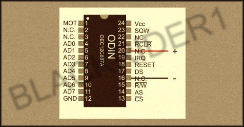
The pinout can be found at https://www.betaarchive.com/forum/viewtopic.php?t=22000, in particular in this image. Pin 16 is negative, and pin 20 is positive. Pin 16 has continuity with motherboard ground. Pin 20 has continuity with the larger surface of the coin cell, which is generally positive. Probably the crystal is connected to pins 2 and 3.

It doesn't smell too bad, and controlling the temperature so it's mostly melting and not burning plastic helps. I'm not going to recommend it because plastic fumes might be unhealthy, and I certainly wouldn't want to do this on a regular basis. But the repair was a success. The PCI slot is fine too, with only very minor cosmetic damage to the outer surface.

Monday, October 12, 2020

Fix for Tseng ET3000AX SVGA card displaying monochrome

This is a Micro-Labs VGA Solution, an ISA super VGA card based on the Tseng Labs ET3000AX. It seems to be a reference design because other brands of cards also exist with the same board layout. It displayed in monochrome on the SVGA monitor.

At first I thought the switches on the back were set incorrectly. They tell the board what kind of monitor is connected and whether it's primary or secondary. They're documented here, but basically they all need to be off. That tells it a that it's the primary card, a "multisync analog monitor" is connected, and a secondary monochrome card may or may not be present. Up, away from the circuit board, is off.

The switches seemed to make no difference. So, I thought the board was broken. But no, the VGA connector standard changed. Those switches only talk about colour and monochrome regarding TTL monitors, using the DB9 connector. The VGA monitor is detected via monitor ID bits according to the old VGA connector standard. The current standard doesn't include those and instead uses an EEPROM providing information about the monitor. It seems that based on what the board detects on those ID bits, it can go into monochrome mode. All the palette entries get transformed via gray-scale summing, making everything black and white. This even happens if you try to set the palette via int 10h.

A software solution is coloron.com, which uses int 10h functions to switch the card to colour mode from DOS. Another solution is to boot with the monitor disconnected. This doesn't only mean power-on, but also if you reboot via the reset button or control-alt-delete. I opted for a hardware solution, cutting the circuit board trace between those connector pins and the rest of the card:

One last thing. The old VGA connector standard has a key at pin 9, meaning no pin there in the male and no hole there in the female. Now that is +5 V DC supplied to the monitor for the identification EEPROM. You might want to drill a hole there in the connector to avoid breaking pins on more modern VGA connectors.

Monday, October 05, 2020

Telequipment D54 oscilloscope bad MPS6518 transistor in sweep-gating bistable

My Telequipment D54 oscilloscope didn't show a trace. Instead, if I turned up brightness all the way there were some very faint blobs which changed a bit with the horizontal position adjustment. If I pulled the plug, the spot appeared coming from the left of the screen. This is similar to when trigger stability has been turned up and it is not being triggered, but stability couldn't make it work and even external X input mode did not work.

The service manual (available at radiomuseum.org) contains schematics and a detailed circuit description.

Clearly the horizontal deflection circuit was pushing the beam all the way to the left. I first removed JFET TR107 and connected a resistor to ground from the sawtooth output. This affected the voltage at the collector of TR108, and the horizontal deflection amplifier worked as expected. But there was still no spot on the screen. I assumed that was due to blanking.

The fact the CRT was blanked and even external X input didn't work made me focus on the sweep-gating bistable built around TR105 and TR106 transistors. After probing it a bit I unplugged TR105, an MPS6518 transistor, and to my surprise the base seemed open circuit. I don't know what made it fail there. Putting in a 2N2907A made it work. This replacement was very easy thanks to the fact all the transistors are socketed. Here's the right side board with the timebase circuitry, a closeup on TR105, and the bad MPS6518 transistor:


For completeness, here's the left side board, with the two channel inputs, vertical amplifiers, and trigger circuitry which provides an input to that sweep-gating bistable:


Friday, October 02, 2020

DEC KA650 (MicroVAX III / 3500 / 3600) error 62 can mean a bad keyboard connected to QDSS

My MicroVAX produced no output via the QDSS. I saw the monitor flash as if the QDSS was initialized, but video output appeared. Instead text went to the serial console of the KA650 CPU board. There, at the start of self test, I saw an error:

?62 2 08 FF 00 0000


According to the KA650 CPU Module Technical Manual, this is:

62 2004 E254 console QDSS mark_notpresent self test r0 self test r1 ****

It appeared at the same time as a keyboard beep. At the end of self tests there was the ominous "Normal operation not possible" warning. Swapping the LK201 keyboard fixed the problem. The keyboard causing the problem had all 4 LEDs lit, while the working keyboard had them all unlit except for a flash during initialization. There is no more error, and QDSS console works fine.

The MicroVAX can still boot NetBSD/VAX 1.3_BETA from the RA90 drive. Digital sure built this stuff to last!

The known failing parts are the RD53 drives. They can spin up with the trick of disconnecting the head actuator coil at startup, but have many read errors. I'll try reformatting them.

Thursday, September 24, 2020

Netbooting SunOS on a SPARC workstation from Ubuntu 20.04

The general procedure for booting a Sun SPARC workstation over the network is well documented. I liked this guide.The post here exists to document ways in which things break in modern Ubuntu and changes which need to be made. I was booting a SPARCstation ELC.

First you need an IP address. It is best to choose a name, add that line to /etc/hosts, and use the name whenever possible.

The boot process starts with the workstation requesting its IP address via Reverse Address Resolution Protocol (RARP). This simply works. Install the rarpd package and put the address in /etc/ethers.

You can now load boot (like kvm/stand/boot.sun4c) or the kernel (kvm/stand/vmunix) via TFTP. Note that the file name is the IP address followed by period and the architecture, capitalized, like C0A8017B.SUN4C for a SPARCstation ELC at 192.168.1.123.

In either case the next step is an answer from bootparamd. Install the bootparamd package, but it won't see the requests, because they're broadcasts and not sent to the server's IP address. You need to add -r to OPTIONS in /etc/default/rpcbind for bootparamd to see the requests. For some reason the lines adding to options weren't expanding ${OPTIONS}, so I had to set them all at once. It will then answer. You must supply both root and swap values in /etc/bootparams.

After that the final step is NFS. Install nfs-kernel-server. SunOS will want NFS and rpc.mountd version 2 protocols, which are disabled. In /etc/default/nfs-kernel-server add --nfs-version 2,3,4 to both at the start of RPCNFSDCOUNT (because RPCNFSDARGS won't make any difference) and in RPCMOUNTDOPTS. Note that /etc/exports requires directories, so to share a swap file you need to share a directory containing it.

If you sent boot via TFTP, it will make a bootparamd request and then load the kernel via NFS. That might be faster than loading the kernel via TFTP, because TFTP is simple and inefficient. The kernel makes another bootparamd request, and then mounts root and swap. What happens afterwards is up to what's in the root file system.

Don't forget to restart daemons after changing configuration files.

When creating devices in the root file system, ./MAKEDEV std is insufficient. You need ./MAKEDEV pty for telnet or xterm, and ./MAKEDEV win for the windowing system. The MAKEDEV script worked fine from Linux. The arch -k error is harmless unless you're using a sun4m system.

SPARCstation ELC repair

The SPARCstation ELC is a SPARC workstation built into a monochrome CRT monitor. It is fanless, and gets quite hot, which is bad for electrolytic capacitors. I suspect that also some particular capacitor models used are bad.

Accessing the computer motherboard (under the cover at the back of the top) is very easy. Unfortunately, disassembling the rest isn't very convenient. Maybe the design tried to make it convenient at first, and then changes defeated that.

Before disassembling further, consider the shock and electrocution hazards. Obviously the line voltage side of the power supply is dangerous. The secondary side is dangerous too, because besides supplying safe voltages to the computer, it also supplies higher voltages to the monitor. The main monitor board uses those to make even higher voltages, and sends some of these to the CRT socket board. Due to capacitors, voltages can persist even when the device is turned off and unplugged.

The first problem was the power supply, the board to the right when viewed from the rear. It seems like it could be possible to lift out, but the speaker bracket screwed into its bottom prevents that. So the whole side needs to be freed and moved outwards.

The power supply was pulsing. This can happen when an SMPS detects a fault, shuts down and restarts, but that's not what was happening here. The -12 V rail had excessive ripple, and I replaced its 100 µF 16 V filter capacitor (the missing C528 in the photo) to fix that, but it wasn't causing the problem either.


Just guessing I saw the 100 µF 35 V capacitor near what seems to be the SMPS controller IC. The board in that area was browned due to heat around various holes, so it makes sense that the capacitor may have been ruined by heat. Also, a failure in power supply to that IC could cause the symptoms. After testing the theory by temporarily placing a capacitor in parallel, I replaced the capacitor and fixed the problem.


Now the picture was barely visible. The firmware screen has black text on a white background, but the text was just a bit darker than the background. Replacing the two visibly leaking pairs of back to back 100 µF 10 V capacitors at the bottom of the CRT socket board took care of that.It turned out those transistors, labelled ITT 895 115C, near the corner of the board were bad as well. According to NTE's cross reference, 2N4401 was a good substitute. I don't know why they failed. I thought maybe I damaged them by accidentally solder bridging surface mount tubular C417S to the neighbouring resistor on the underside while replacing the rightmost capacitor, but that solder bridge apparently needs to be there. I also replaced some other capacitors but am not sure any of that was necessary. This board is probably the worst for capacitors because it is in its own RFI shield box inside the monitor.


Note that the CRT socket board requires the RFI shield to make ground connections. The main ground area visible at the CRT socket and the three tabs to the left of it need to be connected by wires if you remove that shield and want to power on the monitor.

Finally there was some vertical foldover at the top. It was interesting to note that its start stayed in place as vertical size and position was adjusted. Multiple guides about this problem with CRTs in general say that the prime suspect is the pump-up capacitor. The vertical deflection circuit needs a pulse of higher voltage to overcome inductance and quickly move the beam back to the top. This is accomplished via a charge pump, which charges a capacitor in parallel with the supply, and then connects it in series, to provide that higher voltage. That was another one of those 100 µF 35 V light blue capacitors, like in the power supply (the large cap in this photo). Here are the definitely bad components:

If you want to see more photos, take a look at the album.

Friday, September 04, 2020

Fixing Whirlpool part 3378207 to make dishwasher start washing reliably

A dishwasher doesn't simply recirculate water while washing. It tries to separate solids coming off the dishes from the water, and recirculate only the water. Some dishwashers have filters. This dishwasher has a soil separator. First, a chopper breaks up any large particles. Then part of the water being pumped by the wash impeller goes through the plastic doughnut surrounding it, where baffles try to trap particles. Later, when the dishwasher pumps out water, it pumps from the soil separator, sending the particles down the drain.

The outlet of the soil separator connects to the drain pump via the drain pump cover. Also, the outlet of the soil separator has a simple valve operated by water pressure. Under that little cover to the right is a diaphragm which is pushed down by a spring to open the passage. When pressure builds up, it acts against the spring, pushing the diaphragm upwards, and pulling a rubber cone which blocks the passage.

But, how does that pressure build up in the first place, while the passage is open? I'm assuming it builds up due to the drain impeller spinning the wrong way. Both the wash and drain impellers are on the same shaft, and the current function depends on the rotation direction, determined via the motor start winding.

However, if water leaks out elsewhere, then pressure may not build up enough to push up the diaphragm and seal off the passage. That Whirlpool 3378207 drain pump cover has a rubber gasket on top. It has a thin plastic ridge surrounding that gasket, to keep the gasket in place. That ridge breaks off, and then pressure stretches the gasket, allowing water to leak out. The result was that sometimes the dishwasher would fill with water normally and not start washing, even though the pump was running. It's surprising that enough water can escape that way to cause this, but apparently it can.

If I stopped and restarted it while full of water, it always started properly. I guess the big pulse happening when the pump starts provided enough pressure to move the diaphragm, but the slow pressure increase happening as it was filling didn't.

I cut two thin slices from a copper water line, and soldered them into the appropriate shape for holding the gasket in place. The gasket had been stretched a lot, but I managed to squeeze it into place.