Friday, March 29, 2013

Mercury ME-DPF24MG digital photo frame reverse engineering

I got two Mercury ME-DPF24MG digital photo frames at the Leamington Zellers liquidation sale at 70% and 80% off the yellow tag price. They're nice 2.4" photo frames with a 320x240 LCD, rechargeable battery, a magnetic back, and a leg for standing the frame up on a desk. Some reverse engineering has already been done by others, but it's incomplete and the frame cannot be used as USB controlled display yet. The frame is also similar to the Technaxx Magno, which has been investigated more thoroughly but still cannot be used as a display.

Basic information


The frame has 4 megabytes of flash memory. The manual claims "32 MB", but I guess they mean 32 megabits. Phack from st2205tool-1.4.3 does a check for the amount of memory, and quits with "Expected response 8 on cmd 1, got 0x1f!" because the frame reports more memory than expected. Here is the external memory map, in terms of 32 kilobyte (0x8000 size) pages:

0x000-0x07F flash, starting with firmware in pages 0 and 1.
0x080-0x2FF unused
0x300-0x37F LCD
0x380-0x3FF 4 pages repeating, similar to firmware
0x400- address space repeats, probably because bank register ignores bits

The area at 0x380 seems to contain a firmware for a different photo frame. The menus are smaller than in the true firmware, implying it is for a lower resolution. Maybe it is ROM inside the chip? I did not investigate that area further.

The read command adds two to the low byte of the page number. As a result, a normal read starts right after the firmware. I dumped the firmware by reading in page 0xFE, because when firmware adds 2 to that number, it gets 0. I used 0xFE, not 0xFFFFFFFE because the firmware only adds 2 to the least significant byte of the page number.

The chip is probably a Sitronix ST2203U. It is definitely not a ST2205U because the DMA controller is different. I wasn't able to find a full User's Manual for that chip, but the ST2205U and ST2202U manuals are helpful. RAM is at 0x80-0x880 internal addresses, meaning there is only 2 kilobytes.

The LCD controller is unknown, and probably similar to Ilitek ILI9325C. The command number is 16 bit, with the most significant byte first, and coordinates are input the same way.  To talk to the LCD, set DRR to $300, send commands to $8000 and send data to $C000. Here is a sequence for setting a rectangle: C=$20, D=Y1, C=$51, D=Y1, C=$51, D=Y2, C=$21, D=X1, C=$52 D=X1, C=$53, D=X2, C=$22, followed by data with 3 bytes per pixel. This is untested.

Sunday, March 24, 2013

ROM dumping via the sound card

Once I got code running on the RCA RC3000A, the first task was dumping the TCC760 boot ROM and the SST39VF1601 firmware flash. The resistor I soldered for entering USB boot mode provided a convenient connection point for GPIO_B[22]. The chip runs at 2.5V, and that voltage should not be too high for line in. I carefully used an alligator clip to connect it to the tip of a 1/8" plug:

I transferred data serially using a simple ARM assembler program. Zeroes are a short pulse and ones are longer pulses. There is a short pause between bits, and a longer pause between bytes. Here is an example of 11000101 binary. I sent the least significant bit first because right shifts conveniently move it into the carry flag.
Dumping the two megabyte flash chip took an hour and a half. That's not a problem, so it's not worth investing effort in a faster communication method. For larger amounts of data, the TCC76X USB device controller would be a better choice. It seems very easy to use.

The 4KB TCC76X boot ROM has MD5 value 2579641d5be434eea15f4ec3c27a5f53. It implements USB boot mode and secure modes. However, it is not part of the normal operation of the RCA RC3000A. The boot mode is set 000, and execution starts from the SST39VF1601 firmware flash.

The 2MB firmware flash has MD5 value 89ae93fedd7fc5dff0f118aebdd4c7b6. Text strings identify it as "Thomson D100", "V2.20" and "2006.07.13". Apparently unused space with 0xFF bytes starts at 0x92E00, though there is a small chunk used at 0xFE000-0xFE0B2. This means there should be plenty of space for adding a second firmware for dual boot.

Friday, March 22, 2013

Telechips TCC76x USB boot

In my previous post I opened up my RCA RC3000A and enabled USB boot on the Telechips TCC760 SoC. I'm now able to run code on it. The USB boot mode is a bit different than on later Telechips devices which are supported by the Rockbox tcctool utility. The last parameter is not the SDCFG register value, but the start address. Here is a bit of information about the USB boot mode.

All communication is in 64 byte packets. The first packet contains parameters for the USB loader routine. It must be 64 bytes, but all that matters is the first four 32-bit words:
  1. Must be 0xF0000000. If it does not match, the loader will try to use the next packet as the parameter packet, and so on, repeating. 
  2. The number of data packets, or in other words, total data size divided by 64. The loader will receive this number of 64 byte data packets after the parameter packet, and store them sequentially in memory.
  3. The destination address. The loader will store the first data packet starting at this address and store other data packets after it. The loader has no capability for performing the special actions needed to write to flash, so this must be RAM.
  4. The start address. Once the loader has received the specified number of data packets, it will jump to this address.
Note that since SDCFG is not configured, the SDRAM cannot be used and the upload should be to SRAM. The SRAM is 64 kilobytes from 0x30000000 to 0x3000FFFF, and it's also mapped to appear at 0x00000000 to 0x0000FFFF. The boot ROM is 4 kilobytes and copied to the start of SRAM, and it must not be overwritten while it is running there. You can start code at 0x00001000 or 0x30001000. The following tcctool entry can be used:

{"rc3000a",  "RCA RC3000A",                     0xb001, 0x00001000, 0x00001000 },

Thursday, March 21, 2013

RCA RC3000A disassembly and USB boot enabling

The RCA RC3000A is a small boombox with MP3 playback and recording. There is 512M flash, support for SD cards and USB storage devices, an FM radio and line in. Opening it up is kind of difficult due to plastic clips at the inner ring, around the hole. I finally got it open by applying force at the thinnest part at the front. Note how the front and speakers are attached to the top with screws, so only the bottom black part is removed.

Here's a closeup of the main board. There isn't much to see, because it is obscured by copper shielding foil and a speaker assembly.

More can be seen after removing the foil and speaker assembly. However, it's not very interesting. That's just the data flash and 2 MB of SDRAM. The SoC running it all must be hiding on the other side.

Detaching the circuit board is easy. However, the SoC is still hidden behind the LCD support.


After carefully removing the LCD support, I can see that the SoC is the Telechips TCC760. The datasheet is available!

Here's the TEA5767 FM radio:

This is the CS42L51 CODEC. To the left, R59 through R60 are 47 kΩ pulldown resistors which set the TCC760 BM (boot mode) bits to 000, meaning NOR boot without encryption. Making the right side of R60 high at reset time will change BM to 010 and select USB boot instead.

This can also be done on the other side. The capacitor pin closest to the speaker connector is +2.5V and the bottom short trace near the corner of the foil is BM1. I'm using a resistor rather than a short because the same pin is used for LRCLK for the CODEC. Yeah, it's messy, but it's temporary. I'd like to install a switch after I figure out how to run code.

Here's what shows up in Device Manager:

It might be possible to use the Rockbox tcctool program to upload code. A single one line change adding the device to the device list enables uploading, but I have not been able to confirm that any uploaded code actually runs.

The USB device ID is supported by the TeleChips firmware download driver vtcdrv.sys found in iAUDIO_COWON_D3_Upgrade_V4.53GL. There is also a VtcUsbPort.dll in the upgrader. Using these would require reverse-engineering the API. I'm hoping a simple change to tcctool will make this work.

Monday, November 19, 2012

Some bad Verbatim MCC 004 DVD+R discs

I took advantage of a deal at Staples to get a 100 pack of Verbatim MCC 004 DVD+R discs. The 50 pack was good before. Unfortunately, the 100 pack has some damaged discs. I tried to write at 8x and first noticed the problem when speed failed to rise to 8x at the usual spot. Instead, the top speed was 6x. Even verification was slowed down in some areas.

I looked at the recording surface, thinking I probably wouldn't notice anything. The damage was very obvious: many shiny points on the disk surface. When looked at more carefully, they look like short lines, so they're probably scratches. I was careful when handling the spindle and discs, so this must have happened before they were in my possession. I wonder if the spindle was subject to shock or if this is a defect from the factory.

Surprisingly, the PIE/PIF scan wasn't too bad. I would have expected more PI failures. However, there certainly were a lot more PI errors than on discs from the other pack.

Update


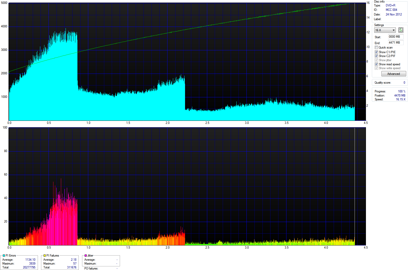
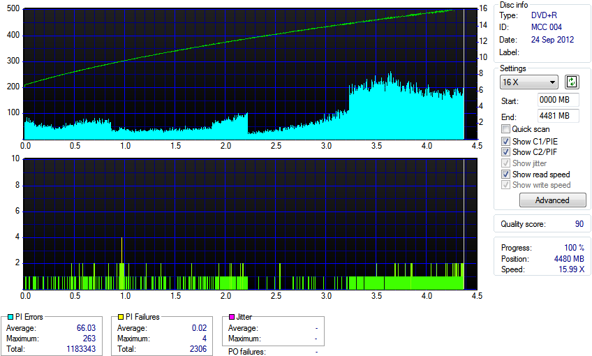
I made a mistake in assuming that the problems I was having with the first few discs were just due to the visible spots. Even the discs without visible damage are of low quality. There are read speed decreases over large areas of the disc, and PIE/PIF scan results are much worse than with previous good Verbatim discs. After some online research, I found that these the infamous PAP6 discs. My previous good discs were PAPA. That's the start of a code you can see on the transparent area in the middle. Here are two photos comparing PAP6 and PAPA. It's hard to make good photos of this, because it's embossed transparent plastic lettering in transparent plastic. Note how the PAP6 disc has air bubbles in the plastic.


Unfortunately, according to online information, you need to open a package to see if it contains PAP6 or PAPA discs. This means Verbatim media cannot be trusted these days. What trustworthy brands are left? Taiyo Yuden? I used to think that it's weird how some people insist on that brand. Now, it seems they were right. Unfortunately, those cannot be found in local stores. Fortunately, hard drive prices have dropped so much that this is a good time to give up on optical media.

Why the drive slows down

I normally do PIE/PIF scans at 5x, because of the increase in errors at higher speeds. At that speed, the PAP6 discs don't seem too terrible. The total PIF count is very high, but the maximum tends to be below 2. At 16x I get a very different picture. Here's a comparison of PAP6 and PAPA discs at 16x.


Thursday, November 15, 2012

Religious images are fine when viewed as mythology


As I was appreciating the Noah’s Ark display at the Niagara Falls Winter Festival of Lights, I asked myself a question: why was I enjoying it?

The image comes from a story about a terrible atrocity, which involved the killing of many people and animals.  It’s also something that very obviously didn’t happen according to the geological record. Believing that the Great Flood happened is delusional, and thinking that such mass killing is good is terribly wrong. Because of such things, serious worship of that God is both inaccurate and immoral.

The image wasn’t bothering me because I was looking at it as something from a myth. In other words I was looking at it as a fictional story.  That’s similar to how I was enjoying the Disney displays. With such a perspective, objections relating to religion become irrelevant.

This seems like a good thing. Openly accepting religious stories and imagery as fictional mythology is better than trying to suppress them. For example, look at various past religions. People don’t care about suppressing the Greek or Norse mythology. Instead, it’s just something that’s appreciated and played with. Things like that enrich culture.

Wednesday, November 07, 2012

Using sed to copy Firefox RES settings to Chrome

Reddit Enhancement Suite settings are stored in a JSON file in Firefox and an SQlite database in Chrome. As a result, one cannot simply copy a file to copy settings from Firefox to Chrome. I like doing twisted things with sed, so I used it to transform the JSON file into an SQL file that can be imported via sqlite3:

sed 's/[^\]"\([^\"]*\)":/\necho -n "INSERT INTO '\''ItemTable'\'' VALUES('\''\1'\'',X'\''" ; echo ~~~/g; s/`/\\`/g' store.json | sed 'sX~~~\(.*\)$X-n \1 | iconv -f UTF-8 -t UTF-16LE | od -vt x1 | sed -n '\''s/^[0-9]* //; ${ x; s/ //g; s/\\n//g; s/0a$//; s/$/'\'\\\\\'\'');/p; }; H;'\''X' | sh > res.sql
cat ~/res.sql | sqlite3 chrome-extension_kbmfpngjjgdllneeigpgjifpgocmfgmb_0.localstorage

You can find store.json in your Firefox profile. The Chrome extension ID can be seen in chrome://chrome/extensions when you enable developer mode, and then you can find the database among your Chrome configuration files. I didn't test this extensively, but it seems to work well so far.

Tuesday, October 30, 2012

Dumping SMRAM

While investingating EIST on my GA-P35-DS3R motherboard, I found P-state changes use special I/O ports which trigger system management mode (SMM). To investigate further, it is necessary to look at SMM code that runs when accesses to ports 0x880 and 0x882 are intercepted.

The first step is to obtain the code. There are two possibilities: extracting it from the BIOS and dumping it from SMRAM. I chose to dump SMRAM. That will show what is undoubtedly actually being run, and it will also dump values of variables.

Since this deals with access to memory, the P35 northbridge chip needs to be examined. Intel provides the 3 Series Express Chipset Family datasheet (PDF). The DRAM controller registers described in section 5.1 can be dumped using "sudo lspci -xxx -s 00:00.0 > P35_DRAM_registers.txt". They are listed in table 5-1.

The value of the SMRAMC register at 0x9D is 0x0A. As expected, G_SMRAME is set to enable SMRAM, but surprisingly, the D_LCK bit is not set. This means that software is free to set the D_OPEN bit and access SMRAM. The compatible SMM space bits are hard-wired, causing memory between 0xA0000 and 0xBFFFF to be used as SMRAM. This overlaps with VGA graphics memory, but that is not a problem because the northbridge can direct accesses appropriately.

The next thing to check is the ESMRAMC register at 0x9E. It's value is 0x39. The H_SMRAME bit is not set, so the low SMRAM at 0xA00000 is not remapped. However, T_EN is set, so according to TSEG_SZ, the top 1 MB of memory is also reserved for use as SMRAM. This TSEG is set as uncachable via an MTRR, so that's the part that's probably being used as SMRAM.

$ cat /proc/mtrr
reg00: base=0x000000000 (    0MB), size= 2048MB, count=1: write-back
reg01: base=0x07ff00000 ( 2047MB), size=    1MB, count=1: uncachable


One could abuse caching to mess with SMM (PDF). However, the D_LCK bit is clear, so there is no need to resort to such trickery. It should be possible to simply set the D_OPEN bit and access that memory.

The first obstacle is the CONFIG_STRICT_DEVMEM. Ubuntu and most other Linux distributions enable it, because unrestricted root access to /dev/mem is considered a security hole. With it enabled, memory at 0xA0000 can be dumped because it is within the first megabyte, but the TSEG at the end of RAM cannot be dumped.

The protection is enabled when the kernel is compiled, and it can only be disabled by recompiling or otherwise modifying the kernel. However, it's possible to load a module which provides another similar device without the protection. It would be natural to base that driver on drivers/char/mem.c, and someone has already done this, creating fmem. After compiling the module and loading it via run.sh, memory can be freely dumped via /dev/fmem.

The only remaining obstacle is the inability to access SMRAM from outside SMM. Fortunately the D_LCK bit is not set, so one can simply set D_OPEN. Here are commands displaying the SMRAMC register, setting D_OPEN, and confirming that the register changed:

$ sudo setpci -s 00:00.0 0x9D.b
0a
$ sudo setpci -s 00:00.0 0x9D.b=0x4A
$ sudo setpci -s 00:00.0 0x9D.b
4a


Now, it is possible to dump SMRAM via dd:

$ sudo dd if=/dev/mem bs=64k skip=10 count=1 of=smram.a0000.bin
1+0 records in
1+0 records out
65536 bytes (66 kB) copied, 0.00113763 s, 57.6 MB/s
$ sudo dd if=/dev/fmem bs=1M count=1 skip=2047 of=smram.tseg.bin
1+0 records in
1+0 records out
1048576 bytes (1.0 MB) copied, 0.0154848 s, 67.7 MB/s


It's probably a good idea to afterwards clear D_OPEN in the SMRAMC register, so that SMRAM has some protection again. This can be done via "sudo setpci -s 00:00.0 0x9D.b=0x0A". Feel free to try to dump the same memory while D_OPEN is cleared. Without D_OPEN, the resulting files have all bits set, showing how SMRAM cannot normally be accessed.

The dumps I got definitely contain the SMRAM. The first 64k of the TSEG dump contains structures documented in chapter 34 of Volume 3 of the Intel® 64 and IA-32 Architectures Software Developer Manual. The SMI entry point is at 0x8000. SMM starts out in a mode similar to real mode, and the code there sets up for an entry into protected mode. Saved state can be seen toward the end of the 64k segment. For example the SMBASE register is at offset 0xFEF8, containing 0x7FF00000 as expected.

That's all for now. I may post more if I find something interesting in the SMRAM.