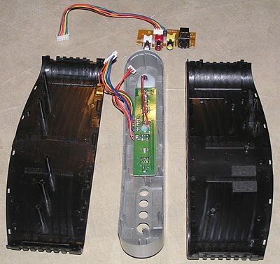
- Remove the silver front. It is only held by clips. Push inwards on the black part near the silver while pulling the silver part away. Start where it's easiest and go from there. You can put folded up paper in the gap to keep it open. The front will remain attached by cables.
- Separate the black parts of the case. Once the front is off, these clips are obvious.
- Unplug the cables going to the front from the main circuit board.
- Unscrew the small circuit board for the front input, and unplug its cable from the main board.
- Unscrew the screws holding the main board and the screws holding RCA connectors to the back. Remove the main board
Photos
The top of the main board shows the through-hole components and the back of the RCA jack circuit board. The socketed chip is a EM78P156EL microcontroller.

The bottom shows the surface mount components. The chips are 4000-series CMOS. The three along the bottom are 4052L. Each contains two four-channel analog multiplexers. The chip above them is an HEF4053B. It contains three two-channel analog multiplexers.

Here is the rest of the device. Note how except for the RF modulator, there's no shielding. Even the video signal from the front panel connects via ordinary wires. Nevertheless, the switch does not seem to degrade video quality.

The Story
I just got a PH61153 video selector switch. It has four inputs, supports composite and S-video and stereo audio and has an RF modulator. The best part is that it can automatically switch to the highest priority input which has a video signal, and so I can basically hide it and forget about it.
I got it from XSCargo. They were the only local store that had it in stock, and they certainly had what seemed like a good price ($19.95). Unfortunately, the low price only reflected the low quality. First I noticed that that Philips wasn't mentioned anywhere. Then I noticed that most of the them were badly scratched and scuffed, and one had something rattling around inside. Finally, when I bought one and brought it home, I found that one of the inputs didn't work. The switch never auto-switched to the first input, and if I manually switched to it I got no composite video or audio.
I didn't like the idea of going back to XSCargo. It was a long drive, and the replacement could again have some issue. At this point, I didn't want to open up the switch and so I first measured resistance at the inputs. Unlike the other inputs, the broken input had an open circuit on all three RCA jacks. Based on this, I concluded that the problem was probably a bad connection, and not a burned out part. So, I decided to open up the device.
The problem turned out to be a crack on the back circuit board. The RCA connectors on the back are all mounted the back circuit board, and the S-video connectors are mounted on the main board. The back circuit board has large square holes for the S-video connectors. As a result, it is only connected to the main board via four fingers. One of these fingers had cracked. That's not surprising when you consider how some RCA connectors can be very tight and hard to fully seat or unplug. It was an easy fix.


